
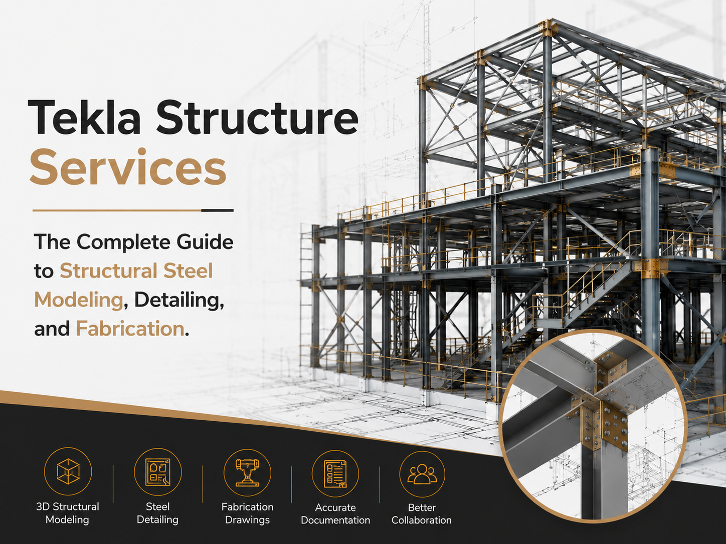
Introduction to Tekla Structure Services
If you’ve ever managed a structural steel project, you already know the pain points: drawings that don’t match on site, fabrication errors that cost weeks of rework, and endless back-and-forth between engineers, detailers, and fabricators.
Tekla BIM services exist to solve exactly this problem. They bring structural steel modeling, detailing, and fabrication documentation together in one accurate, coordinated digital model — so everyone from the design team to the guy running the CNC machine on the shop floor is working from the same information.
This guide walks through everything Tekla BIM services actually involve, how the workflow comes together from kickoff to final steel erection, and why so many contractors, fabricators, and engineering firms have made Tekla Structures their standard tool for steel construction.
Steel projects touch a lot of hands before they’re finished — structural engineers, architects, MEP consultants, detailers, fabricators, and erectors all need to work off the same information without stepping on each other’s toes. When that information lives in scattered 2D drawings, small misunderstandings turn into expensive mistakes.
Tekla’s approach is to put everyone on the same 3D model, so the conversation shifts from “what did the drawing say?” to “what does the model show?” That shift changes how projects run day to day, and it’s a big part of why Tekla has become the default choice for structural steel work around the world.
Why Structural Steel Projects Need Advanced BIM
Steel construction is unforgiving. Unlike concrete, which can be adjusted somewhat on site, steel members are cut, drilled, and welded to exact dimensions in a fabrication shop long before they ever reach the job site.
If a beam is off by even a few millimeters, or a connection doesn’t line up the way it was drawn, that piece either needs costly rework or a field fix that nobody wants to deal with under a tight schedule.
Traditional 2D drafting simply wasn’t built to catch these problems. A 2D drawing can look perfectly fine and still hide a clash between a beam and a duct, or a connection that physically can’t be bolted together in real life.
Advanced BIM tools like Tekla Structures remove this guesswork by building everything in a true 3D environment, where every steel member, bolt, weld, and plate exists as an intelligent object with real dimensions, material properties, and connection logic attached to it.
How Tekla Improves Construction Accuracy
Tekla Structures is built specifically for structural detailing, which sets it apart from more general-purpose BIM tools. Every model created in Tekla is a constructible model — meaning it represents exactly what will be fabricated and erected, down to bolt patterns and weld sizes.
Because the software understands steel connections natively, it can automatically detect clashes, generate accurate shop drawings, and even produce machine-readable files that feed straight into CNC fabrication equipment.
This level of detail catches errors on the screen instead of on the job site. Coordination happens before steel is ever cut, which means fewer requests for information (RFIs), fewer change orders, and a much smoother path from design to erected structure.
What are Tekla Structure Services?
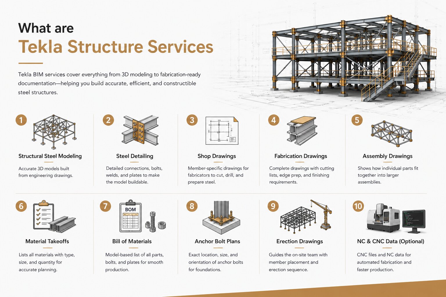
“Tekla Structure services” is an umbrella term covering all the modeling, detailing, and documentation work that’s done using Tekla Structures software. These services take a structural design from engineering drawings all the way through to fabrication-ready documentation. Here’s what typically falls under this scope:
1. Structural Steel Modeling
This is the foundation of any Tekla project. A 3D model is built from structural engineering drawings, representing every steel member — columns, beams, bracing, trusses, and more — with accurate sizes, positions, and material grades. The model becomes the single source of truth for the entire project.
2. Steel Detailing
This is the foundation of any Tekla project. A 3D model is built from structural engineering drawings, representing every steel member — columns, beams, bracing, trusses, and more — with accurate sizes, positions, and material grades. The model becomes the single source of truth for the entire project.
3. Steel Detailing
Once the model is built, detailers add the finer information: connection types, bolt patterns, weld details, and plate sizes. Steel detailing is where a general structural shape becomes a fully buildable component, ready to be fabricated exactly as designed.
4 Shop Drawings
Shop drawings are detailed, member-specific drawings used by fabricators to cut, drill, and prepare individual steel pieces. They include exact dimensions, hole locations, weld symbols, and material specifications.
5. Fabrication Drawings
Closely related to shop drawings, fabrication drawings provide everything a fabrication shop needs to physically manufacture each piece of steel, including cutting lists, edge preparations, and finishing requirements.
6. Assembly Drawings
Assembly drawings show how individual parts combine into larger assemblies before they’re shipped to site, which is especially useful for pre-assembled sections or complex trusses.
7. Material Takeoffs
A material takeoff is a detailed list of every material required for the project, broken down by type, size, and quantity. This is critical for procurement and cost estimation.
8. Bill of Materials
The Bill of Materials (BOM) is generated directly from the model and lists every part, bolt, and plate needed for fabrication, helping fabrication shops plan production runs accurately.
9. Anchor Bolt Plans
10 Erection Drawings
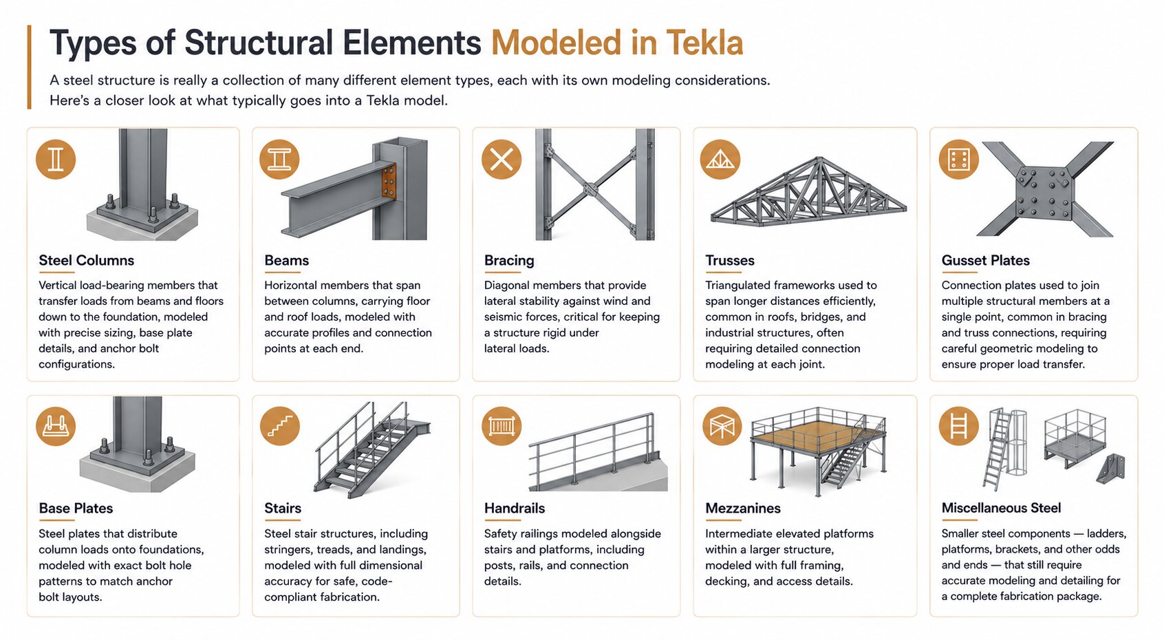
Types of Structural Elements Modeled in Tekla
Steel Columns
Beams
Bracing
Trusses
Gusset Plates
Base Plates
Stairs
Handrails
Mezzanines
Miscellaneous Steel
Benefits of Tekla Structure Services
1. Identify and Resolve Issues Before They Reach the Construction Site
2. Improve Accuracy with Detailed and Constructible BIM Models
3. Reduce Rework and Avoid Costly Mistakes
4. Improve Collaboration Between Design, Fabrication, and Construction Teams
5. Create Faster and More Efficient Fabrication Workflows
6. Reduce Project Costs
7. Minimize RFIs with Clear and Detailed Project Information
Frequently Asked Questions (FAQs) About Tekla Structure
1. What are Tekla BIM Services?
2. What is Tekla Structures used for?
3. Is Tekla better than Revit for structural steel?
4. What is included in Tekla steel detailing?
5. Can Tekla models be used directly for fabrication?
6. Can Tekla integrate with Revit and Navisworks?
Conclusion
As construction projects grow more complex and schedules get tighter, the margin for error in structural steel work keeps shrinking. Tekla BIM services address this directly by moving coordination and accuracy checks into the digital model, long before steel is ever cut. The result is fewer surprises on site, less rework, and a smoother path from design to completed structure.
The software itself is only part of the equation. The real value comes from experienced modelers and detailers who understand structural steel, fabrication realities, and how to keep a project moving smoothly through coordination and revisions. The right partner like BIMPRO brings not just technical skill in Tekla, but a genuine understanding of how steel gets built in the real world.
Whether you’re an engineering firm, a general contractor, or a steel fabricator, professional Tekla BIM services can help your project move from design to construction with fewer delays, fewer errors, and better overall coordination. If you’re ready to see how this could work for your next project, reach out to discuss your specific structural steel needs.
About the Author

Sales Manager
Jinisha Patel is a Sales Manager at BIMPRO LLC with hands-on industry exposure to BIM, Revit, and digital construction workflows. Working closely with AEC firms and project teams has given her a strong understanding of BIM coordination, multidisciplinary collaboration, project requirements, and emerging construction technologies. She writes to turn complex BIM concepts and industry developments into practical insights for AEC professionals.
Contact BIMPRO LLC
