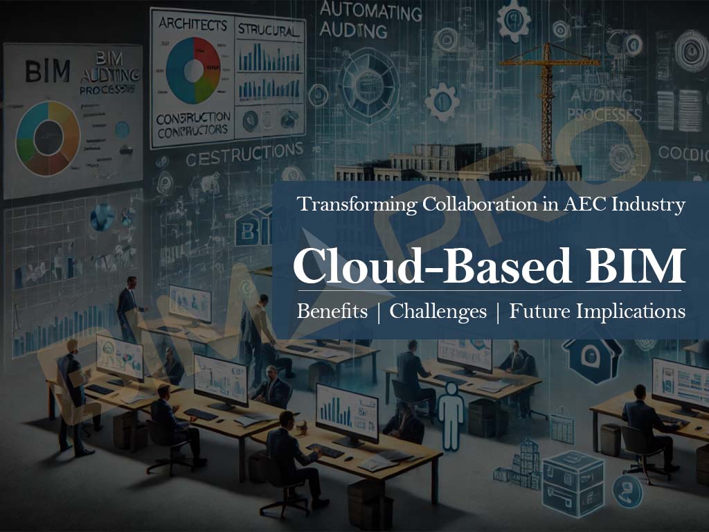
Cloud-Based BIM: Transforming the AEC Industry

Building Information Modeling (BIM) has significantly transformed the Architecture, Engineering, and Construction (AEC) industry by improving project visualization, coordination, and overall efficiency. However, the integration of cloud computing has taken BIM to an entirely new level by enabling real-time collaboration, data accessibility, and seamless project management. Cloud-based BIM allows stakeholders, including architects, engineers, and contractors, to access and work on BIM models from anywhere, ensuring streamlined workflows and enhanced communication. This blog explores the key benefits, challenges, and future implications of cloud-based BIM solutions.
How Cloud-Based BIM Benefits Architects, Engineers, and Contractors
Cloud-based BIM offers many advantages to professionals in the AEC industry. Here’s how it helps:
1. Real-Time Collaboration
Before cloud-based BIM, architects, engineers, and contractors had to send files back and forth, often leading to confusion over which version was the latest. With cloud-based BIM, multiple users can work on the same model at the same time, ensuring that everyone has access to the most up-to-date information. This reduces errors and saves time.
2. Increased Efficiency and Productivity
When all project data is stored in one place and updated in real-time, tasks such as clash detection, design reviews, and coordination become much faster and more efficient. Cloud-based BIM eliminates the need for manual file transfers and speeds up decision-making, allowing teams to complete projects more quickly and accurately.
3. Cost Savings
Setting up traditional BIM systems requires expensive servers and IT maintenance. With cloud-based BIM, companies can use subscription-based services instead of investing in costly infrastructure. This is especially beneficial for small and medium-sized firms that need flexible, budget-friendly solutions.
4. Access from Anywhere
With cloud-based BIM, professionals can access project models and data from any device with an internet connection. Whether working from the office, on-site, or remotely, users can view and edit BIM models in real-time, making project management more flexible and efficient.
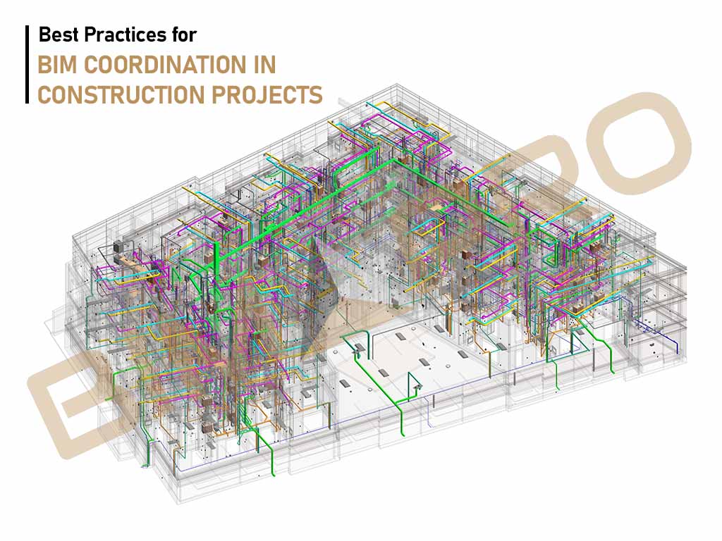
How Cloud-Based BIM Enhances Real-Time Collaboration and Coordination
One of the most powerful features of cloud-based BIM is its ability to enhance real-time collaboration and coordination among project stakeholders. Unlike traditional BIM workflows, where files must be manually shared and updated, cloud-based BIM ensures that updates are instantly reflected for all team members. This reduces the chances of miscommunication and allows for more efficient decision-making.
Cloud-based BIM platforms also offer automated clash detection, helping teams identify and resolve conflicts in the design phase before they become costly issues during construction. Additionally, these platforms integrate with various design and construction software, such as Revit, AutoCAD, and Navisworks, ensuring interoperability and smoother workflows.
Top Cloud-Based BIM Platforms: Features and Comparisons
There are several cloud-based BIM platforms available today, each offering unique features designed to meet the needs of AEC professionals. Some of the most popular solutions include:
- Autodesk Construction Cloud – A unified platform combining BIM 360, Autodesk Build, Autodesk Takeoff, and other tools to streamline workflows, enhance collaboration, and improve construction project outcomes.
- Autodesk BIM 360 – A comprehensive BIM platform that offers cloud storage, real-time collaboration, and project insights. It seamlessly integrates with Autodesk products like Revit and Navisworks.
- Trimble Connect – Designed for construction and design professionals, Trimble Connect provides collaboration tools that enhance communication and coordination. It integrates with SketchUp and Tekla.
- Graphisoft BIMcloud – A solution specifically designed for Archicad users, Graphisoft BIMcloud enables real-time model synchronization and version control.
- Newforma Konekt – Focused on issue tracking and coordination management, “Newforma Konekt” was earlier known as “BIM Track” which improves communication between stakeholders and enhances project efficiency.
- Procore – A widely used construction management software that offers BIM integration, document management, scheduling, and real-time collaboration, helping teams improve project efficiency and reduce errors.
Each of these platforms provides distinct advantages, allowing firms to choose a solution that best fits their project requirements.
Data Security and Privacy in Cloud-Based BIM Workflows
Data security is a significant concern when adopting cloud-based BIM solutions. To ensure secure workflows, leading cloud BIM providers implement robust security measures such as end-to-end encryption, which protects data during transmission and storage. Additionally, role-based access control (RBAC) ensures that only authorized personnel have access to sensitive project information, minimizing the risk of unauthorized access.
Regular backups are another critical aspect of cloud-based BIM security. These backups prevent data loss in the event of system failures or cyberattacks. Furthermore, compliance with industry standards such as ISO 19650 ensures that cloud-based BIM solutions meet stringent data management and security protocols.
Cloud-Based BIM for Remote Project Management and Site Coordination
Remote project management has become increasingly essential in the construction industry, and cloud-based BIM plays a pivotal role in enabling it. With live site updates, contractors and project managers can access the latest construction models from the field, eliminating the need for constant physical meetings or manual data transfers.
Cloud-based BIM also supports issue reporting and tracking, allowing stakeholders to document and resolve design changes in real-time. This enhances communication between site teams and design offices, ensuring that all project participants are aligned with the latest developments.
The Role of AI and Automation in Cloud-Based BIM Solutions
Artificial Intelligence (AI) and automation are playing an increasingly important role in cloud-based BIM solutions. AI-driven capabilities such as automated clash detection help detect design inconsistencies early, reducing rework and improving project accuracy. Predictive maintenance powered by AI analytics can foresee potential construction issues and suggest preventive measures, leading to better project outcomes.
Generative design, another AI-driven innovation, allows architects to create optimized design models based on specific constraints and project goals. This not only accelerates the design process but also results in more efficient and innovative building solutions.
Cloud-Based BIM vs. Traditional BIM: A Comparative Analysis
When comparing cloud-based BIM to traditional BIM, several key differences emerge. Traditional BIM relies on local servers and manual file-sharing, whereas cloud-based BIM provides real-time multi-user collaboration with centralized data storage. The cost factor also differs significantly, as traditional BIM setups require high infrastructure investments, while cloud-based BIM operates on a subscription model, making it more affordable.
Another critical difference is software updates. Traditional BIM requires manual installations and periodic updates, whereas cloud-based solutions receive automatic updates, ensuring users always have access to the latest features and security patches.
| Features | Traditional BIM | Cloud-Based BIM |
|---|---|---|
| Accessibility | Limited to local servers | Accessible from anywhere |
| Collaboration | Requires manual file sharing | Real-time collaboration |
| Cost | High setup costs | Subscription-based, more affordable |
| Security | Managed in-house | Cloud providers ensure encryption and backups |
| Software Updates | Manual updates required | Automatic updates with new features |

Challenges and Considerations When Adopting Cloud-Based BIM
While cloud-based BIM offers numerous benefits, it also presents certain challenges. One of the primary concerns is internet dependency, as a stable and high-speed internet connection is essential for smooth operation. In locations with limited connectivity, this can become a barrier to adoption.
Data security concerns also persist, as cloud-based systems are potential targets for cyberattacks. Firms must ensure they use secure platforms with encryption and access control mechanisms to mitigate these risks. Additionally, a learning curve exists for professionals unfamiliar with cloud-based workflows, requiring training and adaptation efforts.
Integration with existing systems can also be challenging, particularly for firms that use legacy BIM software. Ensuring seamless compatibility and data transfer between old and new systems is crucial for a successful transition.
The Future of Cloud-Based BIM
- Blockchain for Security and Data Integrity
Blockchain technology will improve BIM by providing a decentralized, tamper-proof ledger for storing and verifying data. This enhances transparency, data integrity, and security, ensuring traceability in design changes and streamlining project approvals and payments through smart contracts. - 5G Connectivity for Real-Time Collaboration
5G will enable ultra-fast, low-latency data transfers, allowing real-time collaboration on large BIM files. This will improve remote access to BIM models, support AI and IoT integration, and make cloud-based BIM more accessible to firms of all sizes. - IoT for Smart Construction
IoT sensors will provide real-time data on construction sites, monitoring parameters like structural integrity, energy usage, and safety. Integrating IoT with BIM will enable predictive maintenance, improve safety, and enhance productivity by optimizing material and equipment usage. - VR and AR for Immersive BIM Experiences
Virtual Reality (VR) will allow stakeholders to walk through BIM models in 3D before construction begins, aiding design validation. Augmented Reality (AR) will overlay BIM models onto real-world sites for better coordination and reduced errors, enhancing stakeholder engagement and project accuracy. - AI and Machine Learning for Predictive Analytics
AI and machine learning will analyze BIM data to predict delays, cost overruns, and automate tasks like clash detection. These technologies will also generate optimized designs, reducing material waste and improving decision-making for more efficient project delivery. - Sustainability and Carbon Tracking in BIM
Cloud-based BIM will help reduce carbon footprints by integrating tools for automated carbon footprint analysis and real-time environmental impact tracking. This will assist in selecting eco-friendly materials and ensuring compliance with green building standards, promoting sustainable construction practices.
Conclusion
In conclusion, cloud-based BIM is changing the way construction projects are managed and executed. Unlike traditional methods, cloud-based BIM allows project teams to work together in real time, no matter where they are located. This means architects, engineers, and contractors can access and update project information instantly, leading to better collaboration and fewer mistakes.
One of the biggest advantages of using cloud-based BIM is the ability to store all project data in one central location that everyone can access. This makes it easier to share important documents, plans, and updates, which helps to avoid delays and miscommunications. Teams can also track progress more effectively and quickly spot any potential issues before they become problems.
Another key benefit is the cost savings and flexibility it offers. Cloud-based solutions don’t require expensive hardware or software, as everything can be accessed online. This helps businesses save money while still benefiting from powerful tools. Plus, as cloud storage is scalable, businesses can increase or decrease their usage depending on project needs, making it a flexible solution for all types of projects.
Overall, cloud-based BIM is making construction projects more efficient, collaborative, and cost-effective. As technology continues to advance, it will become an even more important tool for businesses that want to stay competitive and deliver high-quality projects on time and within budget.


.")