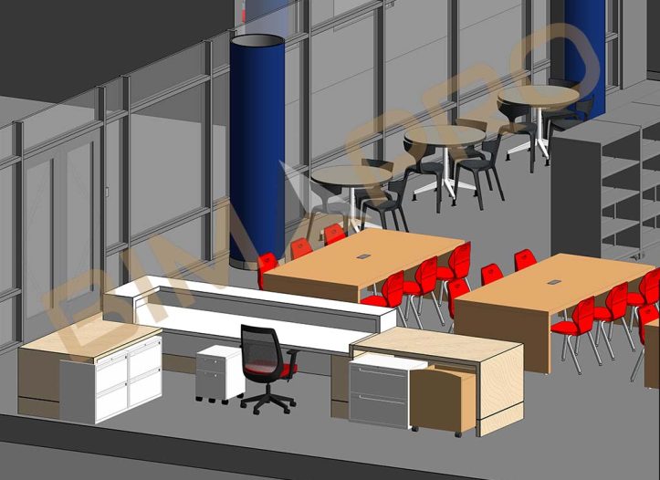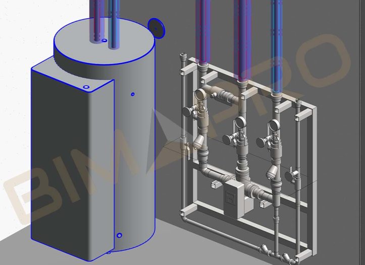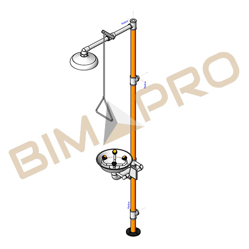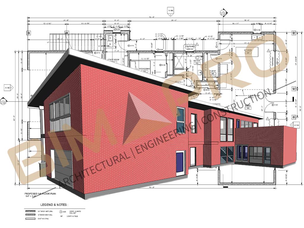
How to Create Custom Revit Families: A Complete Guide

How to Create Custom Revit Families: A Complete Guide

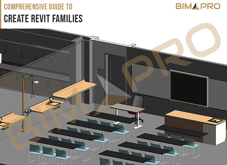
Comprehensive guide to create Revit families _BIMPRO LLC

This complete guide to Revit family creation is the go-to resource for anyone learning how to create a Revit family from scratch, including custom Revit families built for real project needs. Creating Revit families is a crucial skill for anyone involved in Building Information Modeling (BIM), because it lays the foundation for accurate and efficient project workflows. At its core, a Revit family is more than a visual representation of an object; it is a data-rich element designed to be adaptable and reusable across projects. Whether it is a door, window, furniture piece, or custom element, each family is built from a combination of geometry, parameters, and embedded information to meet specific design needs.

By mastering Revit family creation, designers improve project consistency, streamline collaboration, and unlock new levels of design precision. Family creation in Revit is not only a modeling task, it is a way to standardize the components your whole team reuses. For teams that want to maximize efficiency, the option to outsource Revit family creation to experts ensures access to high-quality, standardized components while saving time and cost. That is exactly why many firms turn to professional Revit family creation services rather than building every component in-house.

What Are Revit Families?

Revit families are an integral part of Autodesk Revit, the software used for BIM modeling services. So, what is Revit family creation in plain terms? It is the process of building these digital representations of real-world building components, like windows, doors, furniture, beams, or plumbing fixtures, so they can be placed and reused inside a Revit model.

Think of Revit families as templates for creating BIM objects that appear in your model. These objects are not just shapes. They carry crucial data about the items they represent, such as dimensions, materials, and functional properties, which makes them a key part of building an accurate and detailed digital model. Strong Revit families creation is what separates a tidy, data-rich model from a messy one, which is why it is worth getting the fundamentals right before scaling up.

Types of Revit Families

Each Revit family consists of various “types,” which are different variations of the same basic object. For example, a window family might include types for a 3-foot by 5-foot window, a 4-foot by 6-foot window, and so on. Type creation in a family in Revit is what lets you build these variations without starting from scratch each time, so the model stays tailored to the specific design needs of a project.

When it comes to family creation of Revit components, there are three main types to know: System Families, Loadable Families, and In-Place Families. Each serves a different purpose within the Revit environment.

1. System Families

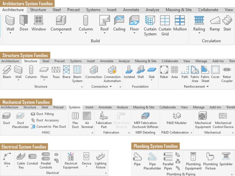
These families are predefined within the Revit software and cannot be created or modified in the same way as other families. System Families include basic architectural, structural, and MEP elements like: Walls, Floors, Roofs, Ceilings, Columns, Foundation elements, etc.

These families are essential building blocks that form the structure of the model. They are typically modified using Revit’s built-in tools (like the Wall tool or Floor tool) but cannot be saved separately or loaded into other projects like Loadable Families.

System Families in Revit

2. Loadable Families

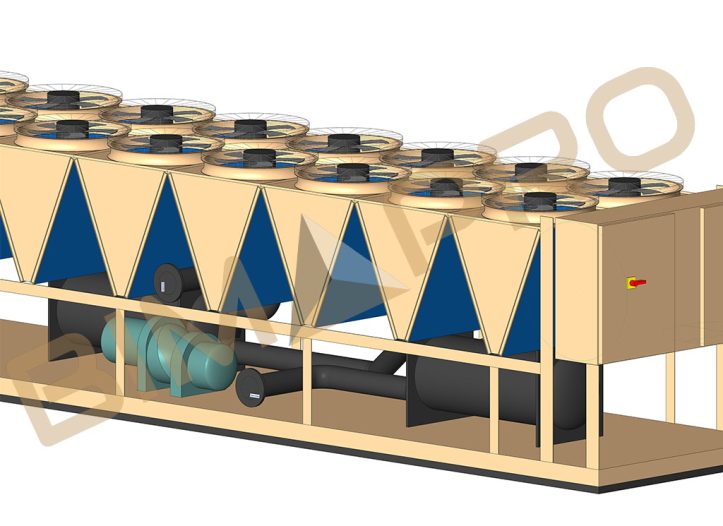
Loadable Families are custom objects that users can create and load into any Revit project. These families are highly versatile and include things like: Doors, Windows, Furniture (chairs, tables), Fixtures (lighting, plumbing), Equipment (HVAC units, appliances).

The beauty of Loadable Families is their reusability—once created, you can save them in a library and use them across multiple projects, ensuring consistency and reducing repetitive work. These families are created from scratch or by modifying existing templates.

MEP System Revit Families

3. In-Place Families

In-Place Families are unique to a specific project. These are created when you need a custom element that doesn’t fit into the typical category of a Loadable Family. They are designed directly within the project and cannot be reused across other projects unless they are manually recreated. These families are often used for highly specialized, one-off components, like: Custom sculptures, Special structural elements, Complex and unique building features.

In-Place Families are flexible and can be modified directly within the project, but their lack of reusability makes them less efficient for large-scale BIM operations.

LOD and Its Impact on Revit Family Creation

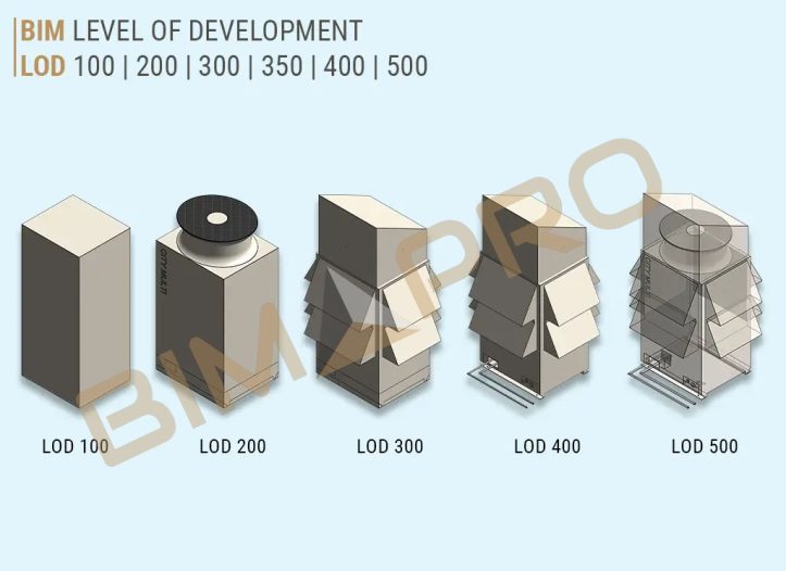
The LOD directly affects the creation of Revit families, as it determines the amount of detail a family should contain and how it will be used in the broader BIM model. Here’s a breakdown of how LOD influences family creation in Revit:

1. LOD 100: Basic Conceptual Families

At LOD 100, Revit families are created for the purpose of demonstrating the concept or massing of the design. The family models in this stage have minimal geometry and are typically represented as simple placeholders or volumes. The primary goal is to provide an overview of the building’s form and function rather than precise specifications.

  • Usage: LOD 100 families are useful in early design stages where the primary focus is on massing studies and spatial relationships.
  • Impact on Family Creation: Families created at this level are not intended for detailed analysis. The geometry is typically low, often represented by basic shapes like boxes, spheres, or simple extrusions.

2. LOD 200: Generic Geometry and Systems Families

At LOD 200, families start to take on more geometric detail. Revit families at this level contain approximate dimensions and may include some additional attributes that help define the size, shape, and location of objects within the model.

  • Usage: LOD 200 families are useful for schematic design, where the project begins to define key elements more precisely, but without full detailing.
  • Impact on Family Creation: Families at this stage include more refined geometry and may also include rough system connections and placeholders for MEP (Mechanical, Electrical, and Plumbing) systems.

3. LOD 300: Detailed and Accurate Families

LOD 300 is where Revit families become fully detailed with accurate geometry and embedded data. Families at this level are typically used for coordination and design development. At this stage, the Revit families contain more complex geometry, material specifications, and dimensions that align closely with the design intent.

  • Usage: LOD 300 families are used for detailed design work, ensuring that all stakeholders can visualize and coordinate with a high level of precision.
  • Impact on Family Creation: These families are created with detailed dimensions, materials, and attributes that can be used for construction documentation. They include elements such as door hardware, fixtures, and structural connections.
BIM LOD (Level of Development).

4. LOD 400: Fabrication-Ready Families

When a Revit family reaches LOD 400, it is fully detailed and ready for fabrication. These families contain all the necessary information for actual construction, including accurate geometry, material specifications, and installation details. This is the most detailed level before the final as-built model.

  • Usage: LOD 400 families are used in the construction phase, where all elements are fully defined and ready for manufacturing or assembly.
  • Impact on Family Creation: At this level, Revit families contain specific fabrication information, such as detailed part numbers, vendor data, and installation instructions. These families are designed with high precision to ensure that the construction team can use them directly for building.

5. LOD 500: As-Built Families

LOD 500 represents the final, as-built condition of the project. The Revit families at this level are used to document the final construction details after the building has been completed. They reflect the actual materials, dimensions, and components used in the building, and serve as a record for maintenance and operations.

  • Usage: LOD 500 families are used for facility management, operations, and future renovations. They provide a precise representation of the completed structure.
  • Impact on Family Creation: Families at LOD 500 are created with extreme accuracy, reflecting the true dimensions and conditions of the as-built elements, including changes made during construction that may not have been present in earlier models.

How Do Revit Families Work?

Revit Families are not just visual representations of objects—they contain embedded data that defines their properties, behavior, and relationships with other elements in the model. There is a stramline process to create Revit family. First, you create the geometry, which defines the shape and size of the object in 2D and 3D space. This could be a simple shape, like a rectangular door, or a more complex shape, like a custom light fixture. Once the geometry is defined, you assign parameters to control the object’s behavior. Parameters are like instructions that define how the object should respond to changes. For instance, a door might have parameters to control its width, height, material, or swing direction. These parameters make the family flexible and adaptable to changes in the design.

Parametric Revit Family Creation

The next step is adding data to the family. This is where the real power of BIM comes in. Revit Families are not just graphical elements—they are full of embedded information. For example, a piece of furniture might have data about its weight, material, manufacturer, and cost. This data can be used for scheduling, cost estimation, and energy analysis, among other things. It ensures that the entire project is well-coordinated, with accurate data flowing seamlessly between design, construction, and operations.

1.Geometry

Geometry refers to the 3D shape of the family. This is the visual part of the family that you can see in the model. For example, the geometry of a door family includes the door’s width, height, and shape. Geometry can be simple (like a rectangular window) or complex (like a custom lighting fixture). The geometry is typically created in Revit’s Family Editor, where you can design the object’s 2D and 3D forms.

2. Parameters

Parameters are the key to Revit’s parametric design, which allows families to adapt based on user input. This is the heart of parametric Revit family creation: change one parameter, such as the width of a door, and every related part of the family updates automatically by the rules you set. These are the dimensions or properties that define how an object behaves and responds to changes in the model. For example:

  • Dimensional Parameters: Controls the size of the object, such as the width, height, and depth of a window or door.
  • Material Parameters: Allows you to assign materials like wood, metal, or glass to your family.
  • Visibility Parameters: Controls whether certain elements of the family appear at different view scales or in different views (e.g., a door might have a different appearance in a floor plan versus a 3D view).
  • Instance vs. Type Parameters: Instance parameters apply to individual instances of the family (e.g., a single window in the project), while Type parameters apply to all instances of a specific type of family (e.g., a specific style of window).

By using these parameters, families become dynamic. When you change one parameter (like the width of a door), all related aspects of the family (such as its size or material) automatically adjust according to the rules defined in the family.

3. Data (Embedded Information)

Revit Families are rich in data. Along with the geometry, families contain detailed information that is crucial for project coordination. This might include:

  • Manufacturer Information: Details about the supplier or manufacturer of a product. Many manufacturers publish ready-made Revit content for their products, so teams often search for branded families, for example, ABL Revit families for lighting, and then adapt them or rebuild them to project standards.
  • Cost Data: Information on the cost of the object, which can be used for budget analysis.
  • Performance Data: Specifications such as load-bearing capacity for structural elements or energy performance for windows and insulation.
  • Scheduling: When a family is placed into the model, Revit can automatically generate schedules to track quantities, dimensions, materials, and other characteristics of the object. This is useful for planning, cost estimation, and logistics.

This data allows teams to work more efficiently, as it automatically populates schedules, helps in procurement, and ensures that the model contains all necessary details for construction.

How to Create Parametric Families in Revit: Step-by-Step

Creating a Revit family requires knowledge of parametric design and an understanding of how to structure the family’s geometry, behavior, and data. Parametric design means using parameters to control an object’s size, shape, and relationships with other objects. For instance, you might build a table family with parameters for height, width, and leg style, so that if the table size changes, the proportions adjust automatically. This is what good parametric Revit family creation looks like in practice.

Once a Revit family is created, you can save it in a library for reuse across different projects, which improves consistency, boosts efficiency, and reduces errors. Below is a clear walkthrough of how to create a Revit family, step by step:

1. Open the Family Editor

The Family Editor is the environment in Revit where you create and modify families. You can access it by creating a new family file. From there, you can start building your family by defining its geometry and parameters.

2. Create Geometry

Start by creating the 2D and 3D shapes that define your family. This can be done using Revit’s drawing tools like lines, arcs, and extrusion commands. For instance, if you’re creating a door family, you’d start by drawing the door panel’s 2D shape and then extrude it into 3D.

3. Assign Parameters

Next, define the parameters that control your family. This includes setting dimensional parameters (e.g., width, height), material parameters (e.g., wood, glass), and any other properties that will make your family flexible.

4. Add Data

If necessary, you can also embed data into the family, such as manufacturer info, cost, and energy performance. This data is important for project coordination and analysis.

5. Load into Project

Once your family is created, you can save it to a library for reuse. You can then load it into any Revit project. When you place the family into the project, you can adjust the instance or type parameters to customize it for your specific needs.

Plumbing Revit families

Benefits of Using Revit Families in BIM

One of the biggest benefits of Revit families is how they support collaboration in a BIM environment. Because Revit is a multi-disciplinary tool, every team member, from architects to structural engineers to MEP specialists, can work from the same families, which keeps the design consistent across disciplines. That reduces errors and miscommunication, since any change to a family, such as the material or dimensions of a door, updates everywhere in the model. Well-built custom Revit families are the backbone of this consistency, and they pair naturally with our wider Revit Drafting Services when projects scale. Using Revit families offers several benefits within the BIM workflow:
  • Consistency: Families keep all components in the model uniform, reducing errors and discrepancies.
  • Efficiency: Once created, families can be reused across multiple projects, saving time and effort.
  • Data Integration: Families carry embedded data for scheduling, analysis, and cost estimation, making the model a comprehensive source of information.
  • Collaboration: Because families are standardized, architects, engineers, and contractors all work from the same components, which means better coordination and fewer misunderstandings.

How Outsourcing BIM Content Creation Services Can Save Time and Costs

For firms without dedicated BIM teams, choosing to outsource Revit family creation is a cost-effective solution. A specialist BIM services provider in the USA can build high-quality, standardized families that match your needs, freeing your team to focus on core design work. Outsourcing also gives you access to experts who stay current on the latest standards. As an experienced BIM Consulting Company, BIMPRO delivers Revit family creation services that follow your templates, naming rules, and LOD requirements, so the content drops straight into your projects. Here is how outsourcing saves both time and cost:

Outsourcing allows you to tap into a pool of experts who specialize in BIM content creation. They are proficient in creating high-quality models, families, and components according to industry standards. This eliminates the need for training internal staff or hiring specialized talent, saving both time and money.

Outsourcing partners often have dedicated teams working on your projects, leading to faster delivery times. Since they focus on content creation, they can handle large volumes of work simultaneously, ensuring quicker project completion and reducing delays on your end.

Outsourcing enables companies to avoid the overhead costs associated with hiring full-time employees, such as salaries, benefits, and training. Instead, you pay for the work done, typically on a contract or per-project basis, which can be more cost-effective than maintaining a large internal team.

As project demands fluctuate, outsourcing provides the flexibility to scale your BIM content creation team up or down without the need for long-term commitments. Whether you need additional help for a short-term project or ongoing support, outsourcing provides the ability to adjust quickly.

Outsourcing to professionals who are experienced with BIM standards reduces the chances of errors in content creation. These experts understand the intricacies of proper modeling, data management, and file formatting, resulting in fewer revisions and rework.

By outsourcing repetitive or specialized tasks like BIM content creation, your internal team can focus on higher-value activities, such as project management, design, and strategic planning. This improves overall productivity and optimizes resource allocation.

Outsourcing firms often have access to the latest BIM software and technologies, which may be costly for smaller companies to maintain internally. This means you get access to cutting-edge tools without having to invest in new software or infrastructure.

Reputable outsourcing partners implement strict quality control processes, ensuring that the BIM content created meets your standards consistently. They follow best practices and adhere to industry regulations, which can improve the overall quality of the content and reduce the need for revisions.

Eye Washer Revit Family

Conclusion

For beginners, learning how to create Revit Families can be challenging but is an essential skill to master in BIM. Once you get the hang of it, it opens up many possibilities for creating customized, reusable, and highly detailed BIM content. It also ensures that the model is both accurate and efficient, providing valuable data for everything from construction to facilities management. As you progress, you’ll be able to create more advanced families, optimize your designs, and streamline your workflow, ultimately contributing to better project outcomes and faster delivery times.

Understanding and mastering Revit Families is crucial for anyone working in BIM. Families are not just graphical elements; they are rich with data and designed to be flexible, dynamic, and reusable. By learning how to create, modify, and utilize Revit Families effectively, you’ll be able to create detailed, accurate models that enhance design, construction, and collaboration, ultimately leading to better project outcomes. Whether you’re an architect, engineer, or contractor, mastering Revit Families will elevate your ability to work efficiently in a BIM environment.

Looking for expericenced Revit Family Creation Services Provider? Contact Us 

Frequently Asked Questions

Revit family creation is the process of building reusable, data-rich components in Autodesk Revit, such as doors, windows, furniture, and fixtures. So, what is family creation in Revit at a practical level? You define the geometry, add parameters that control size and behavior, embed data like materials and cost, then save the family so it can be loaded into any project.

System families are built into Revit (walls, floors, roofs) and cannot be loaded into other projects. Loadable families are custom components you create, save to a library, and reuse anywhere. In-Place families are one-off elements made directly inside a single project. Understanding type creation in a family in Revit helps you get the most out of loadable families, since types let you store many size and material variations in one file.

Parametric Revit family creation means building families whose size, shape, and properties are driven by parameters and formulas. Change one value, such as width, and the rest of the family updates automatically. This is what makes a family flexible enough to reuse across many designs.

Many manufacturers publish ready-made Revit content for their products, which is why people search for branded families like ABL Revit families for lighting fixtures. These are a useful starting point, but it is common to rebuild or clean them so they match your office standards and LOD requirements.

Yes. Revit family training can take your team from basic loadable families into Revit advanced family creation, covering nested families, shared parameters, formulas, and visibility controls. We can train your modelers or handle the family creation for you.

Newforma Konekt: Ultimate Tool in 2025 for BIM Collaboration

Newforma Konekt: Ultimate Tool in 2025 for BIM Collaboration

Newforma Konekt Integration in Revit and Navsiworks_BIMPRO LLC.

The architecture, engineering, and construction (AEC) industry has seen rapid advancements in technology, especially with the adoption of Building Information Modeling (BIM). As these industries evolve, the tools we use for project management and collaboration must adapt. In a groundbreaking development, Newforma recently acquired BIM Track, merging the strengths of both platforms into Newforma Konekt. This unified tool is transforming how project teams manage information, resolve issues, and improve efficiency in BIM workflows.

In this blog, we’ll explore the evolution of Newforma Konekt, its role in modern BIM workflows, and how its integration with BIM Track enhances collaboration, issue management, and project success.

What is Newforma?

Newforma is a project information management (PIM) software designed for architects, engineers, contractors, and other professionals in the architecture, engineering, and construction (AEC) industry. It streamlines the organization and management of project data, including emails, drawings, documents, contracts, and RFIs (Requests for Information), by providing a centralized platform. 
 
Newforma improves collaboration by enabling team members to access and share critical project information in real-time, whether they are in the office or on-site. Its tools facilitate workflows such as document control, submittal tracking, and meeting management, helping to ensure projects stay on schedule and within budget. 
 
Additionally, the software integrates with common tools like Revit, AutoCAD, and Microsoft Outlook, further enhancing productivity and reducing the inefficiencies associated with fragmented data management systems. Widely adopted in the AEC industry, Newforma is recognized for its ability to enhance project visibility, accountability, and efficiency.
Newforma Project Center
Newforma Project Center. (Image courtesy of Newforma.)

What is BIM Track?

The Power of Issue Management in BIM!! BIM Track is a cloud-based issue tracking and collaboration platform tailored for the architecture, engineering, and construction (AEC) industry to improve communication and coordination in Building Information Modeling (BIM) workflows. Designed to integrate seamlessly with popular design and construction software like Revit, Navisworks, AutoCAD, and Tekla, BIM Track enables teams to identify, manage, and resolve issues efficiently throughout the project lifecycle.

The platform acts as a centralized hub where stakeholders can log, track, and prioritize issues, ensuring that every team member has access to up-to-date information, regardless of their location. With its robust reporting and analytics features, BIM Track offers insights into project performance, helping teams identify bottlenecks and streamline workflows. It also facilitates accountability by assigning issues to specific team members and tracking their resolution progress.

BIM Track supports open standards like BCF (BIM Collaboration Format), making it compatible with a wide range of software tools and fostering interoperability across disciplines. By enhancing transparency, reducing rework, and improving communication, BIM Track contributes to delivering projects on time and within budget.

BIM Track Acquisition by Newforma: What It Means for the AEC Industry

In May 2023, Newforma, a leader in project information management (PIM) solutions for the architecture, engineering, and construction (AEC) industry, acquired BIM Track, a prominent cloud-based collaboration platform specializing in issue tracking and BIM coordination. This acquisition represents a strategic move by Newforma to enhance its offerings in project and team collaboration by integrating BIM Track’s advanced issue management and communication capabilities into its platform.

By combining Newforma’s robust project data organization tools with BIM Track’s powerful issue tracking and real-time collaboration features, the merger aims to streamline workflows across the AEC industry. The integration strengthens the ability to manage and resolve design and construction issues while promoting interoperability across multiple software environments through open standards like BCF (BIM Collaboration Format).

This unified platform ensures improved coordination, transparency, and accountability, enabling teams to work more efficiently and deliver higher-quality outcomes. For BIM Track, joining Newforma expands its reach and reinforces its commitment to fostering cross-disciplinary collaboration, solidifying its role as a key player in advancing BIM workflows

Why Newforma Acquired BIM Track?

  1. Enhancing Collaboration Capabilities

The AEC industry relies on seamless communication and collaboration among stakeholders. By acquiring BIM Track, Newforma enhances its ability to facilitate real-time issue management and discussion, bridging the gap between design, construction, and operation teams.

  1. Strengthening BIM Integration

BIM Track’s robust integrations with tools like Autodesk Revit, Navisworks, and Tekla Structures make it a natural fit for Newforma’s portfolio. The acquisition ensures that project data, issues, and documentation are seamlessly linked across platforms.

  1. Expanding Market Reach

With BIM Track’s established presence in the BIM community, Newforma extends its market influence and strengthens its reputation as a leader in AEC project management.

What is Newforma Konekt?

Revolutionizing Project Management in BIM!! Newforma Konekt, the result of Newforma’s acquisition of BIM Track, is a cloud-based collaboration platform designed to streamline communication, document management, and issue resolution for the AEC industry. It connects all project stakeholders—architects, engineers, contractors, and owners—into a centralized environment, ensuring smoother workflows and greater accountability.
Newforma Konekt is built specifically for BIM workflows and it integrates seamlessly with leading BIM tools such as Autodesk Revit and Navisworks, making it an essential tool for any modern construction project.

The Role of Newforma Konekt in BIM Workflows

Newforma Konekt addresses the growing need for effective communication and issue management within BIM projects. It is particularly useful in large-scale, complex construction projects where coordination between multiple teams and disciplines is critical. Here’s how Newforma Konekt fits into the BIM workflow:

1. Centralized Communication

Those days of fragmented emails and lost messages are gone. Newforma Konekt centralizes all project communication in one platform. This enhances transparency, reduces confusion, and ensures everyone is on the same page.

2. Real-Time Issue Tracking and Management

One of the standout features of Newforma Konekt is its issue tracking system. Project teams can track and manage issues in real time, linking them directly to specific elements in the BIM model. This ensures that problems are addressed promptly, minimizing delays and rework.

3. Improved Accountability

Clear documentation of roles and responsibilities within Newforma Konekt helps teams avoid miscommunication. With accountability built into the system, tasks are assigned efficiently, and deadlines are met more reliably.

4. Seamless Integration with BIM Tools

Newforma Konekt integrates effortlessly with popular BIM software like Autodesk Revit and Navisworks, allowing for a smooth data exchange between platforms. This integration ensures that issues, project data, and documents are all connected, reducing the potential for errors or misalignment.

By leveraging Newforma Konekt, BIM service providers can enhance their project delivery capabilities, reduce errors, and improve efficiency. This makes it a valuable tool for companies like BIMPRO LLC, aiming to offer top-tier BIM modeling services.

Newforma Konekt integration with Revit and Navisworks for enhanced BIM collaboration

How Newforma Konekt Enhances BIM Collaboration

The combination of Newforma’s project management expertise and BIM Track’s issue management capabilities creates a tool that addresses key pain points in AEC project workflows. Let’s explore some of the features that make Newforma Konekt invaluable:

1. Issue Management

Issues can be tracked directly within the BIM environment, tied to specific elements in the model. This ensures that issues are clearly identified and resolved quickly, preventing them from snowballing into bigger problems later in the project.

2. Enhanced Collaboration

By providing a shared platform for all stakeholders, Newforma Konekt minimizes communication silos. Teams can easily collaborate in real time, reviewing the same data and providing input across different disciplines, whether they’re in the field or working remotely.

3. Document Control

Newforma Konekt serves as a central repository for all project files. From plans to reports, team members can access the most up-to-date documents at any time, reducing the risk of working from outdated versions.

How to Integrate Newforma Konekt into BIM Workflows

Step 1: Install and Configure the Platform

Start by setting up your Newforma Konekt account and configuring it according to your project needs. Ensure it is integrated with your primary BIM tools like Revit or Navisworks for seamless data exchange.

Step 2: Train Your Team

Conduct training sessions for all stakeholders to familiarize them with Newforma Konekt’s features, including issue tracking, document sharing, and communication tools.

Step 3: Define Roles and Permissions

Assign roles and permissions within the platform to ensure accountability. This prevents unauthorized changes and streamlines workflows.

Step 4: Link Issues to BIM Models

Leverage the integration to link issues directly to model elements. This feature ensures that all issues are contextualized, making them easier to address.

Step 5: Monitor and Optimize

Regularly review the platform’s performance and collect feedback from users. Use insights to optimize workflows and ensure maximum efficiency.

Newforma Konekt Integration in Revit and Navsiworks_BIMPRO LLC

Conclusion: The Future of Collaboration with Newforma Konekt

Newforma Konekt is more than just a project management tool—it’s a game-changer for the AEC industry. Its integration with BIM ensures that teams can collaborate efficiently, resolve issues faster, and deliver higher-quality projects.

For AEC professionals looking to stay competitive in an evolving industry, adopting tools like Newforma Konekt is no longer optional—it’s essential. By streamlining workflows and fostering collaboration, it paves the way for a future where construction projects are not only completed on time but exceed expectations.

Reach out to BIMPRO LLC for BIM services at info@bimprous.com or +1 (346) 508-6588!

Navisworks Vs Revizto – Best Tools for BIM Coordination & Clash Detection

Navisworks Vs Revizto – Best Tools for BIM Coordination & Clash Detection

Navisworks vs Revizto for BIM Coordination & Clash Detection - BIMPRO LLC

Navisworks vs Revizto: Choosing the Best Tool for BIM Coordination and Clash Detection

When you’re managing a BIM project, the software tools you choose can make a world of difference. Navisworks and Revizto are two major players in this space, each with its own strengths and weaknesses. Whether you’re focused on detailed clash detection or ensuring your team is always on the same page, understanding what each tool offers is key to making the right choice. Let’s dive into a detailed comparison of Navisworks and Revizto to help you decide which one suits your project needs.

Navisworks: The Go-To for Detailed Clash Detection

When you’re managing a BIM project, the software tools you choose can make a world of difference. Navisworks and Revizto are two major players in this space, each with its own strengths and weaknesses. Whether you’re focused on detailed clash detection or ensuring your team is always on the same page, understanding what each tool offers is key to making the right choice. Let’s dive into a detailed comparison of Navisworks and Revizto to help you decide which one suits your project needs.

What Makes Navisworks Stand out?

1. In-Depth Clash Detection:

  • Pinpointing Every Issue: Navisworks excels at clash detection. Imagine you’re working on a large hospital project. You’ve got structural steel, HVAC systems, plumbing, and electrical conduits all trying to occupy the same space. Navisworks helps you identify where these elements clash with each other—whether it’s a steel beam running into ductwork or plumbing pipes colliding with electrical conduits.
  • Types of Clashes: Navisworks identifies both hard clashes (physical overlaps) and soft clashes (proximity issues that might cause problems, like inadequate clearances). This dual capability ensures nothing slips through the cracks, giving you the insight needed to address potential problems before they become costly errors on-site.

2. Model Aggregation:

  • Bringing It All Together: Navisworks can aggregate models from different sources into a single, cohesive environment. For example, you can pull in architectural models from Revit, structural models from Tekla, and MEP systems from AutoCAD or other software. This makes Navisworks particularly valuable for complex projects where coordination between various disciplines is critical.
  • Support for Multiple File Formats: It doesn’t matter if your data is coming from .RVT, .DWG, .IFC, or other formats—Navisworks handles them all, allowing for seamless integration and a comprehensive project overview.

3. 4D Construction Simulation:

  • Visualizing the Construction Timeline: With 4D simulation, Navisworks adds the dimension of time to your 3D models. This means you can visualize the construction process step by step, seeing how different phases of the project will unfold over time. For instance, you can map out the sequence of installing structural elements, followed by MEP systems, and then finishes. This helps with scheduling, resource allocation, and identifying potential bottlenecks before they impact the project.

4. Material Takeoff and Quantification:

  • Accurate Material Estimates: Navisworks includes tools for quantifying materials directly from the model. This feature is crucial for cost estimation and procurement. For example, if you need to know exactly how much steel, concrete, or ductwork your project requires, Navisworks can generate these quantities, helping you plan your budget and orders more accurately.

5. Integration with Autodesk Ecosystem:

  • A Unified Workflow: Navisworks is part of the Autodesk suite, meaning it works seamlessly with other Autodesk products like Revit, AutoCAD, and Civil 3D. This integration simplifies workflows, especially for firms already embedded in the Autodesk ecosystem. You can move data between these applications without worrying about compatibility issues.

Challenges with Navisworks

  • Learning Curve: Complex but Rewarding
    Navisworks is powerful, but that power comes with complexity. It’s not the kind of software you can pick up in a day. Users often need substantial training and practice to master its features, especially when it comes to setting up clash detection rules and interpreting the results.
  • Hardware Demands: Need for High Performance 
    Because Navisworks is processing large, detailed models, it can be quite resource-intensive. If your hardware isn’t up to par, you might experience slow performance, particularly when working with very large datasets or running extensive clash detection tests.

Revizto: The Collaboration Powerhouse

While Navisworks is all about detailed technical analysis, Revizto is designed to make collaboration effortless. It’s a tool that prioritizes keeping your team connected and ensuring everyone has access to the latest project information—regardless of their technical background.

Why Revizto is a Collaboration Game-Changer?

1. Real-Time Collaboration:

  • Instant Communication and Updates: Revizto is built for teamwork. Imagine your team is spread across different locations—some in the office, others on-site. Revizto allows everyone to collaborate in real-time, whether they’re marking up a model, leaving comments, or tracking issues. This means faster decision-making and fewer delays caused by miscommunication.
  • Centralized Data: All project data is centralized in Revizto, so you don’t have to worry about version control or fragmented communication. Everyone is working from the same, up-to-date information, which helps avoid costly mistakes and rework.

2. User-Friendly Interface:

  • Accessible to All: Revizto’s interface is designed with simplicity in mind. It’s intuitive enough that even those who aren’t BIM experts—like clients, project managers, or contractors—can easily navigate the platform. This broad accessibility ensures that everyone involved in the project can contribute effectively, without getting bogged down in technical details.
  • 2D and 3D Navigation: Whether your team prefers working in 2D plans or exploring the project in 3D, Revizto makes it easy to switch between these views. This flexibility is especially useful for multidisciplinary teams where different members may have different preferences or expertise levels.

3. Issue Tracking and Management:

  • Keep Everyone Accountable: Revizto’s issue tracking is like a project management tool built into your BIM environment. When a problem is identified—say, a clash, a design flaw, or a construction discrepancy—it’s logged as an issue. You can assign it to the relevant team member, track its status, and ensure it gets resolved. This clear accountability helps keep the project on track and reduces the risk of issues slipping through the cracks.
  • Detailed Issue Logs: Each issue in Revizto is accompanied by rich data, including its location in the model, the date it was created, who it’s assigned to, and any relevant comments or attachments. This level of detail ensures that issues are thoroughly documented and easily trackable.

4. Clash Detection:

  • Simplified but Effective: While Revizto does offer clash detection, it’s not as detailed as what you’d find in Navisworks. However, it’s more than sufficient for many projects, especially those that don’t require deep technical analysis. Revizto’s clash detection is tightly integrated with its issue tracking, so clashes can be quickly assigned and addressed as part of the collaborative workflow.

5. Cross-Platform and Cloud-Based:

  • Work from Anywhere: Revizto’s cloud-based nature means that your team can access the platform from virtually anywhere—whether they’re on a desktop in the office, on a tablet on-site, or even reviewing plans on a smartphone. This flexibility is invaluable for projects where team members are often on the move or working from different locations.

Considerations When Using Revizto

  • Less Detailed Analysis: Not a Replacement for Advanced Clash Detection
    If your project requires highly detailed clash detection or complex model aggregation, Revizto might not fully meet your needs. It’s designed more for enhancing collaboration than for deep technical analysis. For such tasks, you might still need to rely on Navisworks or similar tools.
  • Focus on Communication: More About People, Less About Data
    Revizto shines in environments where communication and collaboration are the top priorities. If your project is highly technical and you need a tool for extensive data analysis, Revizto’s strengths might feel a bit secondary.

Making the Right Choice: Navisworks or Revizto?

Choosing between Navisworks and Revizto ultimately depends on what your project needs most:
  • Choose Navisworks if your project is technically complex and requires detailed clash detection, model aggregation from multiple disciplines, and advanced simulations. It’s the tool for when precision and depth are critical, and you have the resources to support its demands.
  • Choose Revizto if your priority is enhancing team collaboration, keeping everyone on the same page, and managing issues in real-time. It’s the ideal solution for projects where communication, accessibility, and simplicity are key, especially in multidisciplinary teams or projects with less technical oversight.

Conclusion

Both Navisworks and Revizto bring unique strengths to BIM coordination and clash detection. Navisworks is your go-to for detailed, in-depth analysis, making it indispensable for projects where technical accuracy is paramount. Contact BIMPRO LLC for clash detection Services. Revizto, on the other hand, is all about making collaboration seamless and ensuring that every team member, regardless of their technical expertise, can contribute effectively.
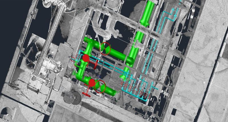
By carefully considering your project’s needs and the strengths of each tool, you can make an informed decision that enhances your BIM workflow, minimizes risk, and ensures successful project delivery.

Looking for expert BIM Modeling Services, reach out to BIMPRO LLC.

Effortlessly Convert PDF to BIM Model: A Comprehensive Guide

Effortlessly Convert PDF to BIM Model: A Comprehensive Guide

Convert PDF to BIM

In the ever-evolving world of architecture, engineering and construction, efficiency is key. Building Information Modeling (BIM) has revolutionized the way projects are designed and executed, allowing for better collaboration and decision-making. However, one of the common challenges faced by professionals in this industry is the conversion of PDF to BIM models. In this article, we will explore how PDF to BIM Services streamlining your workflow and saving valuable time and resources.

Understanding the Importance of PDF to BIM Conversion

1. The Significance of BIM in Modern Construction

BIM has emerged as a powerful and transformative method in modern design and construction. It involves the creation of detailed 3D model with digital representations of buildings and infrastructure. These models not only serve as visualizations but also store essential information about the project, from design and materials to costs and scheduling.
The significance of BIM lies in its ability to facilitate collaboration, reduce errors, and improve project outcomes. It enables architects, engineers, contractors, and other stakeholders to work on a shared platform, making it easier to detect and address potential issues before they become costly problems during construction.

2. The Challenge of PDF Documents

While BIM has become the industry standard for project planning and execution, many architectural plans, and designs are still presented in the Portable Document Format (PDF). PDFs have been widely used for their compatibility and ease of sharing, but they lack the intelligence and interactivity that BIM offers. This separate between PDF documents and BIM technology can lead to inefficiencies in the design and construction process. Architects and contractors often find themselves manually transcribing information from PDF into BIM software, a time-consuming and error-prone task. As a result, there is a growing demand for solutions that can bridge the gap between these two formats.

The Process of Converting PDF to BIM Models

Effortlessly converting PDF to BIM models requires a systematic approach and the right tools. Let’s break down the process step by step:

1. Choose the Right Software

The first and most crucial step is to select the right software for PDF to BIM conversion. Not all software tools are created equal and choosing the wrong one can lead to inaccuracies and frustration down the line.

Look for software that offers robust PDF parsing capabilities and the ability to generate BIM objects accurately. Some popular choices include Autodesk Revit, Bluebeam Revu, and Trimble's Tekla Structures. These tools are specifically designed to handle the intricacies of construction documents and facilitate the conversion process.

2. Importing the PDF

Once you have the selected software in place, the next step is to import your PDF document. The software will analyze the PDF file and extract relevant information. This includes architectural drawings, floor plans, elevations, sections, and other crucial data.

During the import process, it's essential to ensure that the software recognizes and preserves the scale and dimensions of the original PDF. This ensures that the BIM model accurately represents the real-world dimensions of the project.

3. Data Extraction

After importing the PDF, the software will automatically identify key elements within the document, such as walls, windows, doors, and dimensions. These elements are then converted into BIM objects. For example, walls in the PDF will become wall objects in the BIM model, complete with their specifications and properties.

This automated data extraction is where the magic happens. It not only saves a significant amount of time but also reduces the risk of human error. Manual data entry is prone to mistakes, but with the right software, you can trust that the BIM model accurately reflects the information in the PDF.

4. Verify and Refine

While automation is a powerful tool, it's crucial to review the converted data to ensure accuracy. There may be instances where the software misinterprets certain elements or requires manual adjustments depending on the complexity of the PDF document.

Take the time to verify that all BIM objects align with the original design intent. You may need to refine the model by adjusting parameters, adding or modifying elements, or fine-tuning details. This step is essential to ensure that the BIM model is an accurate representation of the project

Industries Benefiting from PDF to BIM Conversion

PDF to BIM conversion has far-reaching implications that benefits several industries within the design and construction ecosystem. Let’s take a closer look at how various sectors can leverage this technology:

1. Architectural

Architects can seamlessly integrate PDF plans into their BIM workflows. This integration streamlines the design process, making it easier to iterate on designs and incorporate changes. Architects can focus on the creative aspects of their work while leaving the technical conversion to the software.

By eliminating the need for manual data entry, architects can spend more time refining their designs and exploring innovative solutions. This not only improves the quality of architectural projects but also enhances their efficiency.

2. Engineering

Engineers play a critical role in the construction process, and the integration of PDF to BIM conversion is equally valuable to them. Engineering firms can use BIM models generated from PDFs to validate and refine their structural and mechanical designs. This ensures that all engineering components align with the architectural plans, reducing the risk of clashes and design errors.

Additionally, engineers can simulate the performance of systems within the BIM environment, allowing for advanced analysis of structural integrity, energy efficiency, and more. This level of integration between PDF and BIM streamlines the engineering phase of construction projects, resulting in more robust and cost-effective designs.

3. Construction

Construction professionals, including contractors and subcontractors, benefit significantly from effortless PDF to BIM conversion. Construction projects involve a multitude of stakeholders, each with their own set of plans and documents. Coordinating these documents and ensuring they align with the BIM model is a challenging task.

BIM conversion simplifies this process. It ensures that everyone is working from the same set of accurate data, reducing conflicts, and discrepancies. Contractors can also use BIM models for clash detection, identifying and resolving issues before they cause delays or cost overruns.

4. Facility Management

PDF to BIM conversion extends its benefits beyond the construction phase to facility management. Facility managers are responsible for the ongoing maintenance and operation of buildings. Having access to accurate BIM models generated from PDFs can be invaluable in this role.

Facility managers can use BIM models to track maintenance schedules, plan renovations, and manage building assets more effectively. The detailed information contained in BIM models allows for better decision-making and resource allocation, ultimately leading to cost savings and improved building performance.

The Future of PDF to BIM Conversion

As technology continues to advance, we can expect continuous improvements in PDF to BIM conversion methods. Here are some key trends and developments to watch for in the future:

The field of BIM and PDF to BIM conversion is dynamic and continually evolving. Software developers are constantly refining their tools to make the conversion process even more efficient and accurate.

Expect to see advancements in machine learning and artificial intelligence (AI) that further enhance the software’s ability to interpret complex PDF documents. These technologies will enable more nuanced data extraction and better recognition of design elements, ultimately leading to higher-quality BIM models

Cloud technology is transforming the construction industry, enabling remote collaboration and data sharing. Future PDF to BIM conversion tools will likely integrate seamlessly with cloud-based platforms, allowing teams to work on BIM models from anywhere in the world.

This level of accessibility and flexibility will open up new possibilities for global collaboration on construction projects. It will also facilitate real-time updates to BIM models as changes occur, ensuring that everyone is working with the most current information.

Mobile devices are increasingly becoming powerful tools for construction professionals. In the future, expect to see mobile applications that can capture data from physical documents, such as blueprints and sketches, and convert them into BIM-ready formats.

These mobile solutions will enable field workers to contribute to the BIM model directly from the construction site, reducing the lag time between design changes and their implementation. This real-time collaboration can significantly improve project efficiency and reduce errors.

Conclusion

Converting PDF to BIM models is a game-changing solution for the architecture and construction industry. It bridges the gap between traditional document formats and modern BIM workflows, offering significant advantages in terms of time savings, accuracy, and collaboration. As technology continues to advance, we can look forward to even more streamlined processes in the future.

In a world where construction projects grow increasingly complex and time-sensitive, the ability to effortlessly convert PDF to BIM models is a competitive advantage that cannot be ignored. Therefore, embracing BIM Modeling Services in your projects is not just about staying ahead of the curve; it’s about delivering better projects, reducing costs, and ultimately, transforming the way we build the world around us.

FAQs - PDF to BIM Integration

BIM, or Building Information Modeling, is a digital representation of a building’s physical and functional characteristics. It’s essential in construction for improved collaboration, error reduction, and better project outcomes.

Architects can seamlessly integrate PDF plans into their BIM workflows, making design iterations more efficient and accurate. This allows architects to focus on creativity while leaving technical conversion to software.

Yes, PDF to BIM conversion can be applied to existing buildings, aiding facility managers in maintenance and renovations. It provides valuable insights into building assets and allows for efficient facility management.

Several software options are available, such as Autodesk Revit, Bluebeam Revu, and Trimble’s Tekla Structures. The choice depends on your specific needs and preferences.

As technology evolves, expect more efficient and accurate methods for PDF to BIM conversion. Advancements in AI, cloud integration, and mobile solutions will continue to enhance this process, improving efficiency and collaboration in the design and construction industry.

3D Laser Scanning – Types | Benefits | Applications

3D Laser Scanning – Types | Benefits | Applications

3D laser scanning services by BIMPRO LLC for precise building measurements
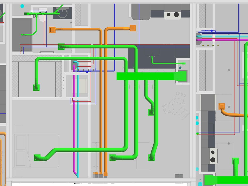
3D Laser Scanning

3D laser scanning techniques have been developed since the end of 1990s for 3D digital measurement, documentation and visualization in several fields including 3D design in processing industry, documentation and surveying in architecture and infrastructure. By using a 3D laser scanner, a tunnel or underground construction can be digitized in 3D with a fast-scanning speed and high resolution up to “mm” level. 

The scanning data consists of not only XY-Z co-ordinates but also high-resolution images, either gray-scale (with reflex intensity data) or color (with RGB data), and then can be transformed into a global co-ordinate system by control survey. Therefore, any rock engineering objects with its as-built situation can be quickly recorded as the 3D digital and visual format in a real co-ordinate system and provides a potential application for 3D measurement, documentation and visualization with high resolution and accuracy.

In modern engineering the term ‘laser scanning’ meaning is the controlled steering of laser beams followed by a distance measurement at every direction. This method, often called 3D object scanning or 3D laser scanning, is used to rapidly capture shapes of objects, buildings, and landscapes.

What is 3D Laser Scanning?

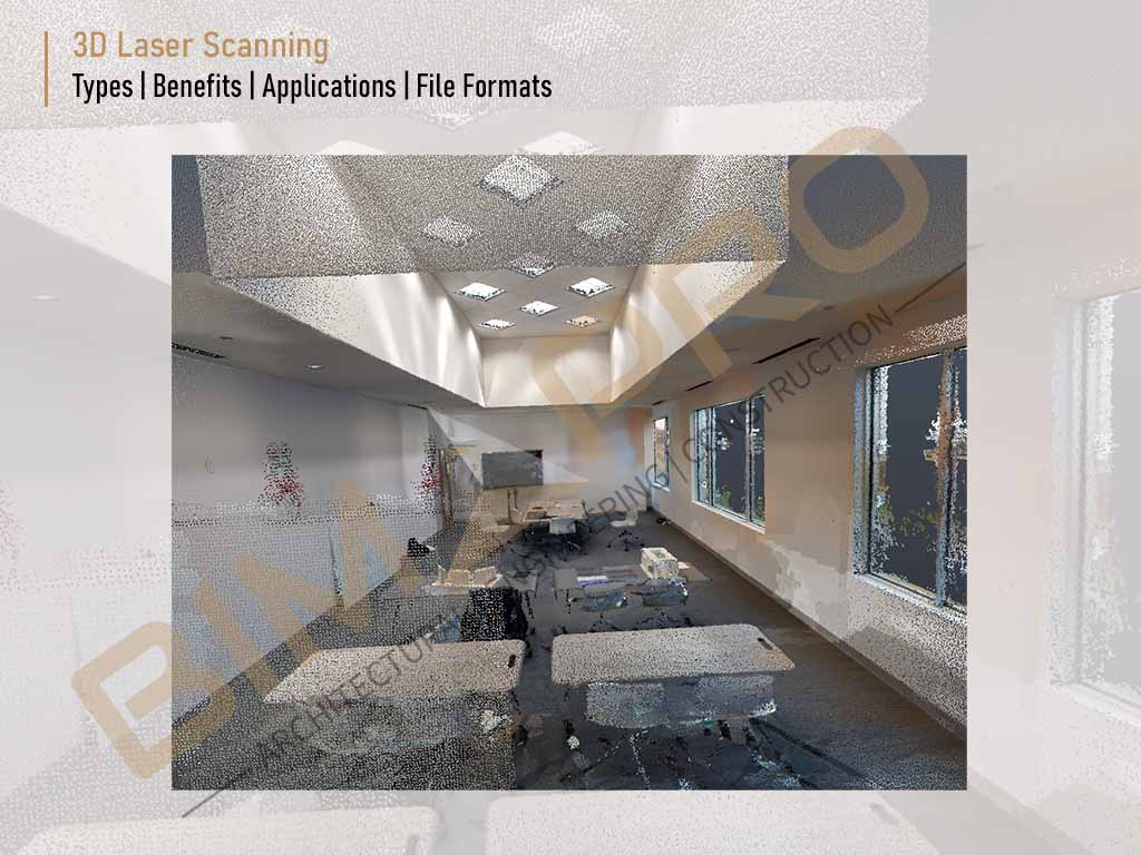
3D laser scanning is a non-destructive, non-contact method of capturing data that can be used for rapid and accurate creation of three-dimensional files, for archiving and digital manipulation. A 3D laser scanner emits a narrow laser beam that hits a target object, gathering millions of closely spaced measurements in a matter of minutes. These scanned measurements are put together and grouped into compressed point cloud databases, which can be processed to generate a 3D dense representation of the object.

3D Scanners Bridging Physical and Digital Worlds

3D scanners are tri-dimensional measurement devices used to capture real-world objects or environments so that they can be remodeled or analyzed in the digital world. The latest generation of 3D scanners do not require contact with the physical object being captured.

3D scanners can be used to get complete or partial 3D measurements of any physical object. The majority of these devices generate points or measures of extremely high density when compared to traditional “point-by-point” measurement devices.

How 3D Scanning Works?

Scanning results are represented using free-form, unstructured three-dimensional data, usually in the form of a point cloud or a triangle mesh. Certain types of scanners also acquire color information for applications where this is important. Images/scans are brought into a common reference system, where data is merged into a complete model. This process — called alignment or registration — can be performed during the scan itself or as a post-processing step.

Computer software can be used to clean up the scan data, filling holes, correcting errors and improving data quality. The resulting triangle mesh is typically exported as an STL (STereoLithography or Standard Tessellation Language) file or converted to Non-uniform Rational B-Spline (NURBS) surfaces for CAD and BIM modeling.

Types of Laser Scanning

1. Airborne Laser Scanning (LiDAR)

Airborne laser scanning (LiDAR = acronym for ‘Light detection and Ranging’, also LIDAR) is a scanning technique for capturing data on the features of, and objects on, the surface of the earth. It is an important data source in environmental studies, since it is capable of mapping topographic height and the height of objects on the surface to a significant vertical and horizontal accuracy, and over large areas. Airborne laser scanning is an active remote sensing technology able to rapidly collect data from vast areas.

2. Terrestrial Laser Scanning

Terrestrial Laser Scanners (TLS) are positioned directly on the ground, or on a platform placed on the ground, and are normally mounted on a tripod. TLS is, in its essence, an improved version of the laser tachometric measurement toolkit (the so-called total station) that is based on the combination of distances and angles measured from a fixed point. Tachometric laser scanners digitize objects of interest with a frequency of 1000 Hz or higher. Each point is measured per one oblique distance and, additionally, two orthogonal angles are measured. Most TLS are long-range devices. Nowadays, a great variety of TLS is available with different range and pulse frequencies.

3. Handheld (portable) Laser Scanning

There has recently been an increase in the application of handheld scanners. Their basic advantage is their portability. Scanners that are attached to light portable stands fall in this category as well, even though they are not ‘handheld’ in the true sense of the word. Primary used in reverse engineering, nowadays they are very often employed in digital documentation of moveable cultural heritage objects.

4. Long- and Short-Range Laser Scanning

Long-range laser scanning is tailored for surveying and monitoring expansive areas or structures. Using high-powered lasers and advanced optics, it covers distances from yards to miles/meters to kilometers. Employing time-of-flight or phase-based technologies, it finds applications in geological surveys, urban planning, infrastructure monitoring, and archaeological site mapping.
Short-range laser scanning focuses on high-precision tasks within confined spaces. Covering distances from centimeters to meters/ feet to yards, it utilizes structured light or laser triangulation. Widely used in industrial metrology, 3D scanning, quality control, and cultural heritage preservation, it excels in capturing fine details with accuracy.

3D Scanning File Formats

TZF: This format is a Trimble scan files in a zipper format. The software exports the current project as a folder with:

• One TZF format file per station
• One TCF format file per station if the station has been acquired with images

E57: This format is a file format specified by the ASTM (American Society of Testing and Materials), an international standards organization. The E57 format supports two types of data: Gridded Data and Non-Gridded Data. Gridded Data is a data which aligned in regular arrays.

E57 Gridded Files: The software exports the current project as one LAS 1.2 format file.

E57 Non-Gridded Files: The software exports the current project as one LAS 1.2 format file.

PTX: This format is an ASCII based for scan file format. The software exports the current project as one LAS 1.2 format file.

LAS, Non-Gridded: The format is public file format for interchanging 3-dimensional point cloud data between users. It is binary-based and has several versions: 1.0, 1.1, 1.2, 1.3 and 1.4. The application exports the current project as one LAS 1.2 format files.

POD, Non-Gridded: The POD (Point Database) file format is Bently Pointools’ native point cloud format. The software exports the current project as one POD format file. Points, color, intensity and normal (if available) information are exported.

RCP: This format file is a project file for Recap from Autodesk. The software exports the current project as one RCP format file.

TDX: TDX is Trimble Data eXchange file format, commonly used in some Trimble software applications like TBC (Trimble Business Center) or RealWorks. The software exports the information listed below:

• Stations with registration sets
• Created panorama(s)
• Measured points
• Leveling information

Benefits of 3D Laser Scanning

3D laser scanning has become an indispensable tool across many industries due to its ability to capture highly detailed and more accurate 3D data. Here are some of the key benefits of 3D laser scanning:

High Accuracy

Laser scanning provides extremely accurate measurements, making it effective for applications where precision is critical, such as engineering, construction, and product manufacturing.

Rapid Data Capture

Laser scanners can quickly collect a large amount of data, reducing the risk associated with scanning high buildings and improving field staff safety.

Non-contact Technology

Laser scanning is noninvasive and doesn’t require physical contact with the object or environment being scanned, making it ideal for fragile, hazardous, or hard-to-reach locations.

Comprehensive Documentation

Laser scanning creates detailed and comprehensive digital records of objects, buildings, or landscapes, which are invaluable for preservation and historical archiving.

Visualization

Data from 3D laser scans can be used to create highly realistic visualizations, aiding in the design, analysis, and communication of complex structures and spaces.

Clash Detection

When integrated with building information modeling (BIM), laser scanning helps identify clashes between design plans and existing structures, reducing costly construction errors.

Applications of 3D Laser Scanning

3D Laser Scanning is used in numerous applications:  Industrial, architectural, civil surveying, urban topography, reverse engineering, and mechanical dimensional inspection are just a few of the versatile applications. 3D laser scanning technology allows for high resolution and dramatically faster 3D digitizing over other conventional metrology technologies and techniques.  Some very exciting applications are animation and virtual reality applications.

1. Construction Industry and Civil Engineering

a. As-built drawings of bridges, industrial plants and monuments b. Documentation of historical sites c. Site modelling and lay outing d. Quality control e. Quantity surveys f. Freeway redesign g. Establishing a benchmark of prre-existing shape/state in order to detect structural changes resulting from exposure to extreme loadings such as earthquake, vessel/truck impact or fire. h. Create GIS (Geographic Information System) maps and Geomatics

2. Reverse Engineering

Reverse Engineering refers to the ability to reproduce the shape of an existing object. It is based on creating a digitized version of objects or surfaces, which can later be turned into molds or dies. It is a very common procedure, which has diverse applications in various industries. Non- contact 3D laser scanning allows even malleable objects to be scanned in a matter of minutes without compression, which could change their dimensions or damage to their surfaces. Parts and models of all sizes and shapes can be quickly and accurately captured. 3D laser scanning for reverse engineering provides excellent accuracies and helps to get products to market quicker and with less development and engineering costs. 3D Laser scanning provides the fast, accurate, and automated way to acquire 3D digital data and a CAD and BIM model of part’s geometry for reverse engineering when none is available. Also, new features and updates can be integrated into old parts once the modeling is accomplished. A practical mechanical and civil engineering application would be to assist in the production of "as built" data and documentation. Currently, many manufacturing or construction activities are documented after the actual assembly of a machine or civil project by a designer or engineering professional. 3D laser scanners could expedite this activity to reduce man-hours required to fully document an installation for legacy.

3. Mechanical Applications

Reverse engineering of a mechanical component requires a precise digital model of the objects to be reproduced. Rather than a set of points a precise digital model can be represented by a polygon mesh, a set of flat or curved NURBS surfaces, or ideally for mechanical components, a CAD solid model. A 3D scanner can be used to digitize free-form or gradually changing shaped components as well as prismatic geometries whereas a coordinate measuring machine is usually used only to determine simple dimensions of a highly prismatic model. These data points are then processed to create a usable digital model, usually using specialized reverse engineering software.

4. Civil Applications

Civil activities could be for a roadway periodic inspection. The digitized roadway data could be contrasted to previous roadway 3D scans to predict rate of deterioration. This data could be very helpful in estimating roadway repair or replacement costing information. When personnel accessibility and/or safety concerns prevent a standard survey, 3D laser scanning could provide an excellent alternative. 3D Laser scanning has been used to perform accurate and efficient as-built surveys and before-and after construction and leveling survey.

5. Design Process

Design process including: a. Increasing accuracy working with complex parts and shapes b. Coordinating product design using parts from multiple sources c. Updating old CD scans with those from more current technology d. Replacing missing or older parts e. Creating cost savings by allowing as-built design services, for example: automotive manufacturing plants. f. “Bringing the plant to the engineers” with web shared scan and saving travel costs.

Conclusion

3D laser scanning equipment senses the shape of an object and collects data that defines the location of the object’s outer surface. This distinct technology has found applications in many industries including discrete and process manufacturing, utilities, construction. Laser scanning technology has matured and developed in the past two decades to become a leading surveying technology for the acquisition of spatial information.

The high-quality data produced by laser scanners are now used in many of surveying’s specialty fields, including topographic, environmental, and industrial. These data include raw, processed, and edited dense point clouds; digital terrain and surface models; 3D city models; railroad and power line models; and 3D documentation of cultural and historical landmarks. 3D laser scanners have a wide range of applications which applicable to very small object to a wide range area.

Frequently Asked Questions

3D laser scanning is a technology that uses laser beams to capture the shape, size, and details of objects or environments in three-dimensional space. It creates a digital representation of the scanned object or area, commonly used in fields like architecture, engineering, surveying, and manufacturing.

3D laser scanning works by emitting laser beams onto surfaces and measuring the time it takes for the laser to return. The scanner records millions of data points, creating a point cloud. Software then processes this point cloud to generate a detailed 3D model of the scanned object or space.

3D laser scanning is widely used in various industries, including architecture, engineering, construction, manufacturing, archaeology, and forensics. It’s employed for tasks such as creating accurate 3D models, inspecting structures, capturing as-built conditions, and documenting historical artifacts.

Two common types are time-of-flight scanners and phase-based scanners. Time-of-flight scanners measure the time it takes for a laser pulse to travel to the object and back, while phase-based scanners measure the phase shift of the laser light.

Two common types are time-of-flight scanners and phase-based scanners. Time-of-flight scanners measure the time it takes for a laser pulse to travel to the object and back, while phase-based scanners measure the phase shift of the laser light.

The raw data from 3D laser scanning is processed using specialized software to create a point cloud. This point cloud can be further processed to generate 3D models, perform analysis, and extract relevant information for various applications.

Comprehensive Guide of Scan to BIM

Comprehensive Guide of Scan to BIM

What is Scan to BIM?

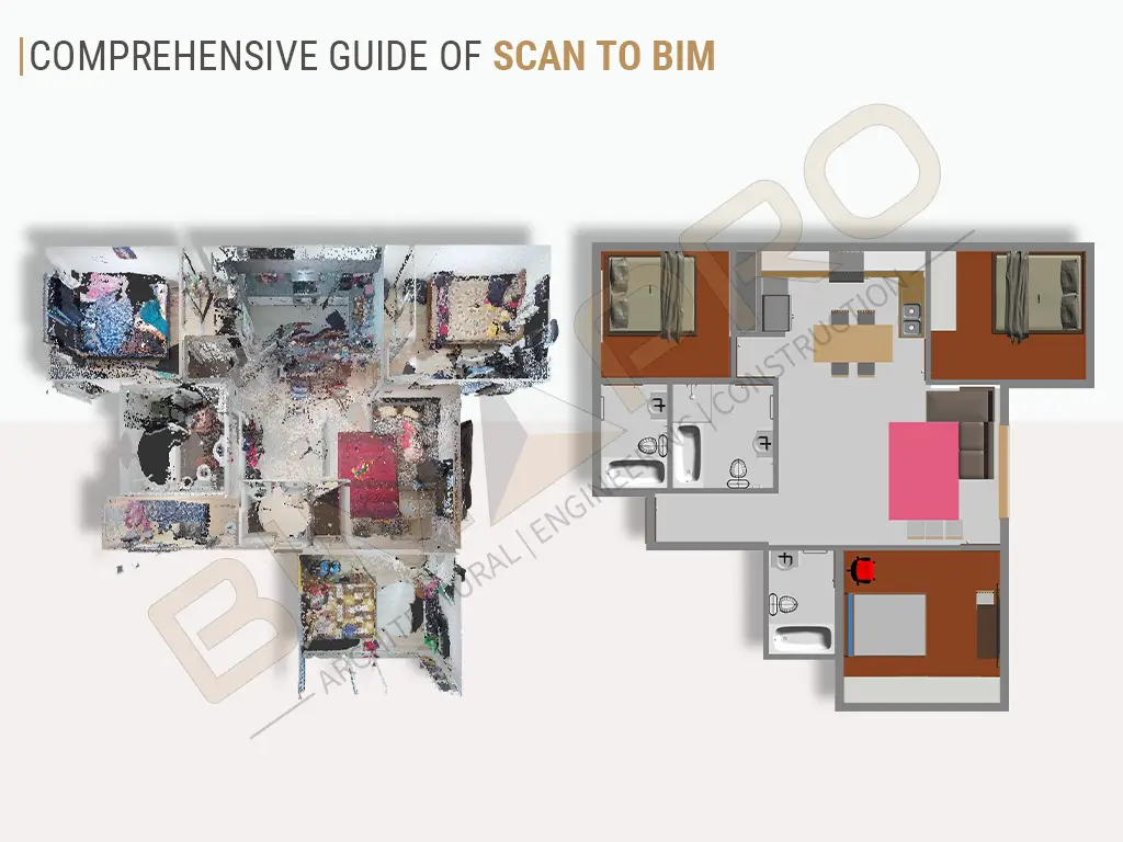
Scan to BIM, also written scan-to-BIM, is an innovative process that uses 3D scanning technologies to capture precise measurements and data of physical structures, and then converts that data into detailed 3D Building Information Models (BIM). So what is Scan to BIM in practice? It is the bridge between a real building and a data-rich digital model. These models serve as accurate representations of the real-world environment and are essential tools for architects, engineers, and construction professionals. Because most projects rely on laser scan to BIM, the result is a 3D scan to BIM model you can measure, coordinate, and build from with confidence.

The significance of Scan to BIM in construction cannot be overstated. The Scan to BIM advantages include improved accuracy, reduced errors, enhanced collaboration, and better project management. By providing a digital twin of existing conditions, it helps projects save time, money, and resources while minimizing risk and improving overall outcomes.

Understanding 3D Scanning

3D scanning is based on the fundamental principle of capturing data points from an object or environment using laser beams or photographs. These data points are then used to reconstruct a three-dimensional digital model with precise measurements, shape, and spatial information. The advantages of 3D scanning include rapid data capture, sub-millimeter accuracy, non-invasiveness, and the ability to capture complex and intricate details. These benefits make it invaluable in various industries, including construction, archaeology, and manufacturing.

Types of 3D Scanning Technologies

Capturing a site in 3D is the first step in Scan to BIM, and three technologies are used to do it: LiDAR, photogrammetry, and laser scanning. Each records existing conditions as a detailed point cloud, with different strengths in speed and accuracy. Laser scanning is the most common for buildings, because a 3D laser scan to the BIM workflow converts its precise point clouds into accurate models. The three methods below show how each one works.

LiDAR Scanning USA

LiDAR (Light Detection and Ranging)

LiDAR uses laser beams to measure distances and create highly accurate 3D models. It's widely used for mapping, topography, and large-scale projects. Image Source: Towill

Photogrammetry_USA

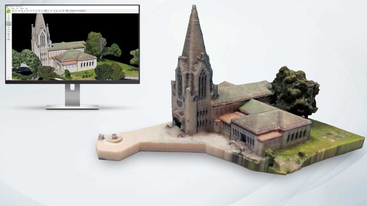
Photogrammetry

Photogrammetry relies on photographs taken from different angles to create 3D models. It's suitable for capturing textures and colors in addition to geometry. Image Source: 3D Natives

Laser scanning services in the USA by BIMPRO LLC, offering accurate as-built models for construction

Laser Scanning

Laser scanning involves the use of laser light to capture millions of data points, resulting in detailed and precise 3D representations. It's often employed for architectural and structural documentation. Image Source: Leica Geosystem

What is BIM?

(BIM) is a digital representation of a building or infrastructure project that encompasses both its physical and functional characteristics. BIM goes beyond 3D geometry and includes information about materials, costs, schedules, and more. It acts as a collaborative platform for stakeholders throughout a project’s lifecycle. BIM offers a multitude of benefits in construction, such as improved communication, clash detection and resolution, accurate cost estimation, and enhanced visualization. It also facilitates sustainable design and better facilities management.

BIM transforms the construction industry by replacing traditional 2D drawings with intelligent 3D models. These models enable real-time collaboration among architects, engineers, contractors, and other stakeholders. The result is more efficient project delivery, fewer errors, and better-informed decision-making.

Integration of Scan to BIM

  • Why Combine 3D Scanning and BIM?

Combining 3D scanning and BIM creates a powerful synergy. It allows construction professionals to start with accurate as-built data, which is crucial for retrofitting, renovation, and improving project accuracy. By integrating these technologies, project teams can streamline processes and reduce the risk of discrepancies between design and reality.

  • The Synergy of Scan to BIM

The synergy between 3D scanning and BIM lies in their complementary capabilities. 3D scanning captures precise measurements of existing structures, while BIM provides a platform for modeling, analysis, and collaboration. Together, they enable professionals to work with a higher degree of accuracy and efficiency.

  • Challenges and Solutions

Integrating Scan to BIM can present challenges, including data interoperability and software compatibility. However, solutions involve using software platforms that support both 3D scanning data and BIM and adopting open data standards to enhance collaboration and data exchange.

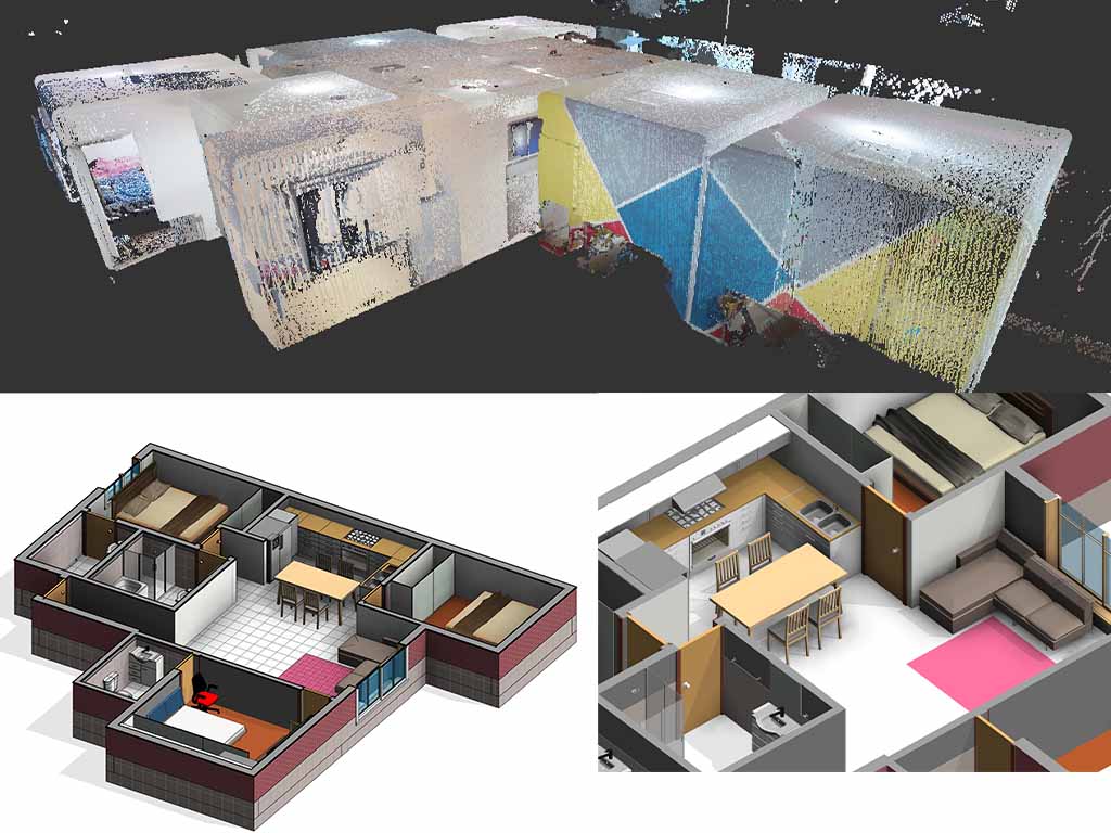
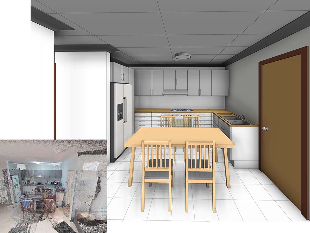
Convert laser scan to BIM Model

Scan to BIM Workflow

Step 1: Pre-Scanning Preparation

Before scanning, thorough pre-scanning preparation is crucial. This step involves conducting a site inspection to understand project requirements, identify key areas for scanning, and assess safety concerns. Additionally, equipment setup is essential to configure scanners, cameras, and other hardware for optimal data collection.

Step 2: Data Acquisition

The data acquisition phase involves the actual scanning process. This may include laser scanning or photogrammetry, depending on project requirements. Various data capture techniques, such as handheld devices or drones, are employed to ensure comprehensive coverage and high precision.

Step 3: Data Processing

Data processing is a critical step in Scan to BIM. It includes point cloud conversion, which transforms raw scan data into usable formats, and cleaning and registration to remove noise and align multiple scans accurately.

Step 4: Model Creation

Using 3D modeling software, the processed point cloud is converted into intelligent BIM objects. This Scan to BIM for Revit step traces the cloud into walls, columns, doors, and MEP elements, the same discipline behind our 2D CAD to 3D Revit Services.

Step 5: Validation and Quality Control

Validation and quality control are vital to ensure the accuracy and integrity of the BIM model. This step involves verifying that the digital model aligns precisely with the physical environment and meets project standards and requirements.

Application of Scan to BIM

This technology has a wide range of applications in various fields. Here are some of the key applications of Scan to BIM:

  • Architectural Design:
    An architectural Scan to BIM service is extensively used to create accurate as-built 3D models of existing buildings and structures. Architects use these models as a foundation for renovations, refurbishments, and additions, working with precise measurements and a clear view of the constraints of the existing building. Demand for architectural Scan to BIM services keeps growing as more firms renovate aging stock rather than build new.
  • Structural Engineering:
    By converting point cloud data from scans into BIM models, structural engineers can analyze the load-bearing capacity, detect potential structural issues, and plan necessary reinforcements or repairs. It also aids in designing retrofit solutions.
  • MEP Systems:
    Scan to BIM is valuable for designing and retrofitting MEP systems in buildings. It helps MEP engineers accurately map the existing conditions of a building, including the locations of electrical, plumbing, and HVAC systems. This information is crucial for designing efficient and well-coordinated MEP systems.
  • Facility Management:
    The 3D BIM models generated from scans provide a comprehensive overview of the building’s components and systems. This information can be used for asset management, maintenance planning, and tracking the performance of building systems over time.
  • Construction and Renovation:
    Scan to BIM assists in construction and renovation projects by providing a precise representation of existing conditions. Contractors can use BIM models to plan construction sequences, ensure accurate fit-outs, and minimize clashes with existing structures. This reduces costly rework and improves construction efficiency.
  • Historical Preservation and Documentation:
    In historical preservation projects, Scan to BIM is essential for documenting and preserving historical buildings and structures. It allows for the creation of detailed 3D models that can serve as a reference for restoration work and historical documentation.

Benefits of Scan to BIM in Construction Projects​

  • Cost Savings
    BIM services reduces construction costs by minimizing errors, rework, and material wastage. Accurate digital models enable more efficient planning and resource allocation.
  • Time Efficiency
    The technology accelerates project timelines by streamlining design, coordination, and construction processes. Faster decision-making and clash detection help avoid delays.
  • Improved Accuracy
    By starting with precise as-built data, Scan to BIM ensures that designs and construction align with the existing conditions. This reduces discrepancies and errors during the project.
  • Clash Detection and Prevention
    One of the significant advantages of Scan to BIM is its ability to identify clashes and conflicts in the early design phase. This proactive approach prevents costly revisions and construction delays.

Read the portfolio: Point Cloud Scan to BIM Modeling for Residence in Texas

Explore our BIM portfolio

3D Laser Scan to BIM Services

Scan to BIM Services: How To Choose the Right Company in the USA

Understanding the process is one thing; delivering it on a live project is another. That is where professional Scan to BIM services come in. Experienced Scan to BIM companies handle the full path from point cloud to coordinated model, so your team gets accurate as-built data without buying scanners or training specialists in-house.

When you compare Scan to BIM companies, look for:

  • Clear level of detail (LOD) agreements, so you know exactly what the model will include
  • Proven Scan to BIM modeling services across architectural, structural, and MEP scopes
  • Sensible, reliable turnaround times
  • Quality control that checks the finished model against the original scan
  • A Scan to BIM company that works to your templates, naming standards, and file formats, so the deliverable drops straight into your workflow

Why teams choose BIMPRO:

  • A USA-based BIM Company delivering Scan to BIM services nationwide
  • Experience across large commercial buildings, residential, and heritage projects
  • Coverage for nationwide work and local requests alike, including searches like Scan to BIM Kingswood and other specific
  • Texas and USA locations
  • A team that scopes the project with you and recommends the right level of detail for your budget

If you need a reliable Scan to BIM service for an upcoming renovation or as-built project, get in touch, and we will scope it with you.

Conclusion

As construction projects become more complex and demanding, Scan to BIM will continue to play a pivotal role in improving efficiency, accuracy, and collaboration within the industry. Its integration with emerging technologies like AI and ML promises even greater advancements in the future of construction. Scan to BIM is not just a technology; it’s a transformative approach that reshapes how construction projects are planned, executed, and managed.

In essence, Scan to BIM is a tool that enhances the capabilities of professionals across various industries by providing them with a comprehensive, data-rich, and visual representation of the built environment. It not only improves project outcomes but also contributes to the overall efficiency and sustainability of the construction and facility management sectors. As technology continues to evolve, Scan to BIM services will likely play an even more significant role in shaping the future of the built world.

Related Blog: Why do contractors use 3D laser scanning? – by Construction Trimble

Frequently Asked Questions

The cost of implementing Scan to BIM varies depending on project size, complexity, and the equipment and software used. However, it’s important to consider the potential cost savings and improved project outcomes that result from its implementation.

Project duration depends on factors such as project scope, size, and complexity. While smaller projects may be completed relatively quickly, larger and more intricate projects may take several weeks or months.

Absolutely, Scan to BIM is particularly valuable for renovations and retrofits. It provides accurate as-built data that helps designers and contractors plan modifications and improvements with precision.

While Scan to BIM is a powerful tool, it does have limitations. It requires skilled professionals to operate the equipment and software effectively. Additionally, challenging environmental conditions, such as extreme weather or limited visibility, can impact data capture.

Commonly used software for Scan to BIM includes Autodesk Revit, Bentley MicroStation, Trimble SketchUp, and various point cloud processing tools like Autodesk Recap and Leica Cyclone. 

The main Scan to BIM challenges are managing very large point clouds, data interoperability between scanning and BIM software, and agreeing on the right level of detail. Choosing compatible software and setting clear standards up front solves most of these Scan to BIM challenges.

The key Scan to BIM advantages are accurate as-built data, fewer errors and clashes, faster coordination, and reliable documentation for renovation and facility management. Together, these advantages reduce rework and keep projects on schedule.

Yes. Scan to BIM for Revit is the most common workflow. After scanning and registration, the point cloud is imported into Revit, where modelers build intelligent walls, columns, doors, and MEP elements that match the real structure.

BIM in Construction Industry

BIM in Construction Industry

BIM in Construction Industry

Building Information Modeling (BIM) has had a profound impact on the construction industry, revolutionizing the entire process of project planning, design, and construction. BIM offers a digital 3D representation that captures both the physical and functional aspects of a building’s facility. This technology encompasses detailed geometric and semantic information from various architectural, MEP (Mechanical, Electrical, Plumbing), and structural disciplines, all seamlessly integrated to create a comprehensive 3D BIM model of the structure.

One of BIM’s key strengths lies in fostering collaborative efforts among all stakeholders involved in design and construction, including architects, engineers, general contractors, and trade contractors. This collaboration takes place within a shared digital BIM platform.

BIM’s transformative impact on the construction industry extends to numerous areas. It enhances team collaboration, optimizes design, detects clashes, estimates costs, manages scheduling, and streamlines facility management. The adoption of BIM within the construction sector continues to grow steadily. This is primarily due to construction companies recognizing the manifold advantages it offers, including improved project outcomes, risk mitigation, cost savings, shortened turnaround times, and heightened efficiency throughout the building’s lifecycle.


BIM Uses in the Construction Phase

BIM uses refer to the practical applications derived from the BIM process. The essential applications of BIM in the construction industry are introduced and further explained below:

  • Existing Conditions Modeling or Field Capturing

A 3D model can be created to represent the current state of a site, a facility, or a specific space. Various techniques, such as modeling software, laser scanning, and surveying methods, can be employed to develop this model. The choice of method depends on project requirements and objectives. Laser scanning, for instance, generates an exceptionally precise 3D point cloud. This data can then be integrated into the BIM model and used either to model the area accurately or to validate existing models.

Explore: Point Cloud Scan to BIM Services

  • Cost Estimation or Quantity Takeoff

A BIM 3D model is valuable for generating precise quantity takeoffs of building materials and components. The 3D model is connected to cost data, enabling the extraction of accurate cost estimates.

  • 4D Modeling

4D modeling is a process utilized to plan and visualize the phased occupancy of construction projects. This technique proves particularly valuable for tasks like renovation, addition, retrofitting, or any project requiring coordinated sequencing of construction activities. The essence of a 4D model lies in integrating the traditional 3D building model with the dimension of time. This integration empowers stakeholders to not only visualize the project’s construction sequence but also to gain a comprehensive understanding of its execution and scheduling.

Explore: 4D Construction Simulation Services

4D Construction Simulation Services in USA
  • Site Utilization Planning

By connecting the information from the 3D model with the 4D schedule, project stakeholders can efficiently communicate spatial and sequencing requirements at the construction site. This integration fosters a clearer comprehension of how diverse elements come together over time, aiding in the early detection of potential conflicts or constraints that might arise during the construction process.

  • 3D Coordination and Clash Detection

Clash detection software is a valuable tool used in the construction industry to coordinate and identify clashes or conflicts between different building systems. It compares the 3D models of various systems, such as architectural, structural, mechanical, electrical, and plumbing, to detect any clashes before the actual construction or installation takes place.

Explore: BIM Coordination Services and Clash Detection Services

BIM Coordination Services - BIMPRO LLC
  • Construction System Design or Virtual Mock-up

3D modeling software is widely used in the construction industry to create, design, and analyze building systems. It enables the detailed development of 3D representations for various components like formwork, glazing, tie-backs, and more.

A significant focus when using this software is on the connections between different building elements. These crucial junctions require collaboration and coordination across various trades. The software allows for in-depth analysis of these connection points.

  • Digital Fabrication

Thanks to BIM technologies, digital fabrication minimizes uncertainties during manufacturing and provides clear instructions for component production, reducing waste. Manufacturers can accurately translate design plans into fabrication instructions, minimizing errors and enhancing efficiency. This technology is applied in areas such as sheet metal fabrication, structural steel fabrication, pipe cutting, and 3D printing for prototyping.

Explore: Shop Drawings Services

  • 3D Control and planning or Digital Layout

Information models are used to position facility components and automate equipment control and movement.

  • Field/Manage Tracking

During construction, commissioning, and handover, Field Management BIM software helps manage tasks, quality control, safety, and document reporting. It’s connected to BIM models and ensures smooth processes.

  • Record Modeling or As-built Modeling

Record modeling accurately portrays the physical conditions, environment, and assets of a facility. It combines BIM models created during design, construction, 4D coordination, and subcontractor fabrication to deliver a comprehensive record model for owners and facility managers.

Why BIM is Important to Construction Managers?

While the design team is often associated closely with Building Information Modeling (BIM), Construction Managers (CM) also play a vital role in ensuring a successful construction project. Even though CMs typically don’t create the BIM model itself, they need a solid grasp of the procedures and technologies used throughout the project’s entire lifespan, not just the design phase.

It’s crucial to oversee the asset from its creation to its operation and eventual decommissioning. Construction managers must understand BIM data thoroughly, contribute to it, and verify its accuracy to make the most of its benefits. They need to use model information and innovative approaches to support new construction techniques, scheduling, costs, quality, coordination, fabrication, sequencing, facilities management, and more. To fulfill these broader responsibilities, construction managers need to embrace new tools, processes, and skills

Benefits of BIM for Contractors

BIM has become a valuable method in the construction industry, offering several benefits that general contractors and subcontractors implement for efficient project outcomes.

  • Enhanced Planning and Design

BIM enables contractors to collaborate closely with architects and engineers during the project’s planning and design phase. This collaboration allows contractors to provide input on constructability and cost-effective solution

  • Streamlined Coordination

BIM improves coordination among various trades by integrating architectural, structural, mechanical, electrical, and plumbing models in platforms like Navisworks. This integration detects clashes and resolves conflicts before construction starts.

  • Accurate Cost Estimation

General contractors and subcontractors can extract accurate quantities of building materials directly from detailed BIM models. This eliminates manual calculations and errors, ensuring precise bidding and procurement.

  • Advanced Construction Simulation and Scheduling

BIM allow platform to integrate construction simulation and scheduling data with the 3D BIM model. This help owners, contractors to optimize project timelines, plan resources, ensuring efficient project execution.

  • On-site Construction Management

BIM allow real time onsite access in digital model which allow contractors to monitor the accurate installation, verify compliance with design intent, and track construction progress.

Conclusion

Utilizing BIM in the construction industry empowers general contractors and subcontractors, enhancing construction execution and coordination. This, in turn, boosts overall project efficiency, mitigates construction risks, reduces cost overruns, and saves time and budget. By integrating BIM with contractors during the early planning and design phases, design errors can be minimized and resolved before construction begins.

References

Read More Related Blogs

3D Laser Scanning - Types, Benefits, Applications - BIMPRO

3D Laser Scanning 3D laser scanning techniques have been developed since the end of 1990s for 3D digital measurement, documentation and visualization …

Navisworks vs Revizto for BIM Coordination & Clash Detection - BIMPRO LLC

Navisworks vs Revizto: Choosing the Best Tool for BIM Coordination and Clash Detection When you’re managing a BIM project, the software tools …

Newforma Konekt Integration in Revit and Navsiworks_BIMPRO LLC.

The architecture, engineering, and construction (AEC) industry has seen rapid advancements in technology, especially with the adoption of Building Information Modeling (BIM). …

MEP Coordination Services for Residential Apartment Project

MEP Coordination Services for Residential Apartment Project

Setup of MEP coordination services framework presents a significant challenge for complex Apartment projects. Today, residential projects are so complex that specialized contractors and consultants with experience are needed to execute them within the given budget and timeframe.

However, due to a lack of awareness of various digital tools available in the market, consultants and contractors often use semi-digitalized methods for executing MEP projects, in which design coordination is done through AutoCAD plans, while the most critical part, clash detection, is done manually.

This approach often results in identifying different service clashes during the execution stage, which leads to rework, time consumption, and cost overruns. Sometimes, the cost of this rework is so high that it negatively affects the project, resulting in cost overruns, time overruns, and reducing the profits of all parties involved.

MEP Coordination Using BIM Technology

In the construction industry, the mechanical, electrical, and plumbing (MEP) systems of a facility can represent up to sixty percent of its total cost. Given this significant figure, coupled with the challenges of routing each of these systems, MEP coordination becomes a high priority in the Residential apartment design of constructions.

This coordination typically involves the trade contractors and other responsible parties such as engineers and VDC coordinators, who work together to integrate their systems into the apartment building. Traditionally, this process involved a time-consuming overlay of drawings to identify clashes and route the MEP systems.

With the development of computer-aided design (CAD), this process became faster and replaced the traditional approach. However, with the introduction of Building Information Modeling (BIM) technologies, new processes have emerged that include clash detection and highly detailed visualizations, taking MEP coordination for Apartment project to the next level.

Some of the BIM software can be used for effective MEP coordination are Autodesk’s Revit, Navisworks, BIM360 Glue, Procore, Tekla, Trimble Connect, and more.

BIM MEP Coordination Services - BIMPRO LLC USA

BIM-based MEP Coordination Services for Apartment Projects

BIM-based MEP coordination services ensure that the MEP systems of the apartment project are designed, coordinated, fabricated, installed and construct correctly and efficiently. BIM coordination services facilitate collaboration among various stakeholders involved in the BIM construction project including architects, MEP engineers, general contractors, MEP contractors, and other trades.

The BIM Model allow all stakeholders a digital representation of physical and functional characteristics of the MEP systems of building’s facility.

MEP Coordination Services - BIMPRO LLC USA
MEP Coordination Process for Apartment Project

The BIM MEP coordination process usually begins with the creation of a 3D model of the building, which includes the architectural, structural, and MEP systems. Each MEP system is then modeled in detail, including ductwork, piping, conduits, and other components.

Explore: MEP BIM Services

The model is then analyzed for potential clashes between different systems or components. These clashes are resolved by adjusting the position or configuration of the affected components in the model.

Explore: Clash Detection Services

Once the coordination process is complete, the final 3D model serves as a basis for generating detailed shop drawings, fabrication models, and installation drawings.

Explore: Shop Drawings Creation Services


  • Use Standard MEP Template

Use company standard MEP template for modeling which include MEP components.

  • Positioning MEP model with Architectural Model

Add architectural model coordinates to MEP model and positioning them by using the “Origin to Origin” approach.

  • Create Levels and Grids for MEP Model

Align the levels and grids of MEP model with the base model (architectural and structural model)

  • Create MEP Worksets

Creating worksets to show and hide the mechanical, electrical, plumbing, fire protection elements for better visualization.

  • Develop MEP-FP Model

Create highly detailed and accurate 3D MEP Model based on the required BIM LOD, BEP (If available), specifications, drawings, and client’s input.

  • Run Clash Detection

Run interdisciplinary Clash detection between architectural, structural, mechanical, electrical, plumbing, fire protection systems and generate clash reports.

  • Review and resolve

All clashes’ elements can be identified by their clash ID and that can be fixed in the Revit file. Some complicated clashes can be reviewed and resolved with the contractors and design team by generating RFI, clash reports and change orders.

MEP Coordination Services - Texas - BIMPRO LLC USA
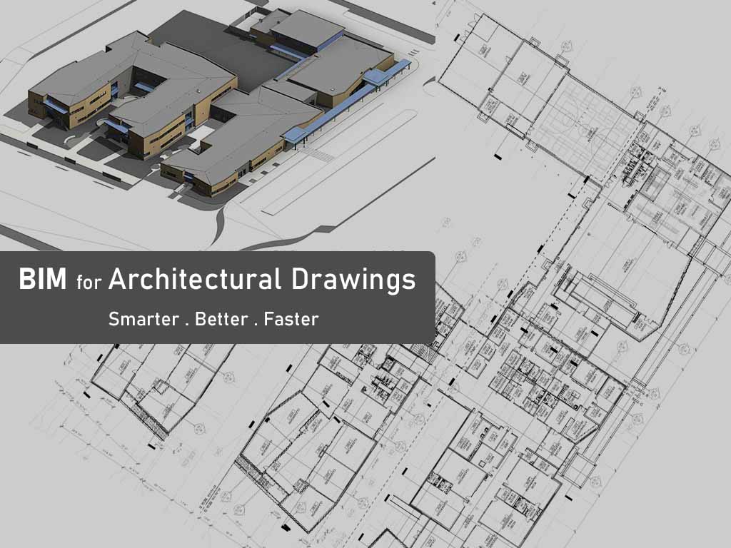
Benefits of BIM MEP Coordination Services

  • Clash Detection and Resolution – Identify and resolve the clash between multiple disciplines before the construction begins.
  • Optimum Space Utilization –  Optimal utilization of available space to maximize functionality of MEP design layouts.
  • Enhance Building Performance –  It ensures that all MEP components works seamlessly throughout the project lifecycle, facilitating energy efficiency, sustainability, operational effectiveness.
  • Save Cost Overrun – Resolution of clash errors in the early phase of design and construction can reduce the reworks, material wastage and facilitate the cost savings.
  • Streamline Construction Schedules – Facilitate smoother construction schedules by minimizing the disruption caused by clashes and delays.
  • Mitigate Risk – It provide safe working environment by eliminating hazards and ensure safety regulations, thus mitigating the risk associated with MEP systems during the construction and operation phase. 
  • Effective Collaboration – It provide a collaborative platform for all team members where they can communicate effectively to facilitate the smooth decision making process.

Conclusion

In conclusion, MEP coordination services are a critical method for apartment’s design and construction project. With the advent of BIM technology, MEP coordination has become more efficient and effective, reducing the risk of rework, delays and cost overruns. BIM software allows all stakeholders to work collaboratively on a project, identify potential clashes and solve them before construction begins. This results in a more streamlined construction process, better quality control and ultimately, successful project outcomes.

References

BIM Implementation Strategies for Small and Medium-Sized firms in AEC industry

BIM Implementation Strategies for Small and Medium-Sized firms in AEC industry

BIM Implementation for SME firms in AEC industry - BIMPRO LLC USA

BIM implementation is increasingly gaining traction. The architecture, engineering, construction, and operations (AECO) industry across United States is rapidly transitioning to a digital landscape, and Building Information Modeling (BIM) has become an integral part of this transformation.

Building industry stakeholders recognize the benefits of virtual prototyping, which allows for more efficient design reviews, greater precision in construction, and the ability to evaluate cost-saving alternatives and other critical parameters.

Small and Medium Enterprises (SMEs) in USA play a vital role in the architecture, engineering, construction, and operations (AECO) industry, and their innovative practices are crucial for implementing Building Information Modeling (BIM) within an Integrated Design framework.

While USA governments encourage BIM-oriented approaches in their state and federal projects across multiple sectors of AEC industry. Small companies’ involvement in common BIM adoption is often insufficient, resulting in a significant BIM-gap that hinders the industry’s overall adoption of innovative BIM technologies in construction.

Encouraging SMEs to adopt BIM can help improve the productivity and economic profitability of the AECO industry, as well as reduce risks for individual firms.

BIM Implementation for SME Firms

Managing the implementation of Building Information Modeling (BIM) for Small and Medium Enterprises (SMEs) is a critical task that requires addressing various risk diversities and identifying the barriers and challenges that can impede the change process.

Although BIM implementation is expanding, it remains slow among SME firms, and larger companies with in-house BIM capabilities typically undertake large and complex BIM projects, utilizing BIM software and technological resources to develop 3D models and coordinate internally to ensure successful project completion.

The architecture, engineering, and construction industry in the USA must overcome several challenges to achieve effective BIM implementation, which involves technology, process, people, policy.

The transition to using BIM is dependent on changing hardware and software, which are essential in the BIM implementation process in the United States.

BIM Implementation for Architectural firms

BIM business transformation can deliver real business benefits, but it requires companies to evolve their current beliefs, culture, technology, and standards. Changing the way infrastructure organizations work today is no small task.

This transformation requires organizational and process improvement, technology adoption, and alignment with overarching strategies and goals to fully realize the organization’s BIM vision.

Critical Factors for BIM Implementation for SME firms

There are many new workflows and procedures that must be planned. Tested and deployed but these high-level BIM implementation areas are critical for generating change in the SMEs organization.

1. Developing Policies and Strategies

The implementation of BIM can be strategically aligned with an organization’s overall goals and objectives to enhance competitive positioning, achieve operational excellence, and ensure effective project delivery. Developing policies and strategies for the implementation of BIM can offer various benefits in this regard.

2. Change Management

The BIM change and adoption program built to deliver the expected benefits in operational performance through program coordination, knowledge transfer, performance management,

and education and training. The AECO industry must invest in training programs and workshops to enable workers to acquire the necessary skills and knowledge to implement BIM effectively.

3. Define Standards and Processes:

Well-defined standards and processes must be established to govern BIM usage in all projects and programs. These standards and processes should support the application of BIM practices and enable stakeholders to operate effectively while adhering to established methods.

4. Integrated BIM Technology

Integrated BIM technology refers to the use of BIM process and model management tools that are seamlessly integrated with enterprise systems. This integration enables the delivery of information in a collaborative environment across the organization and project teams. Also, BIM implementation relies heavily on technology, which includes hardware, software, and other digital tools.

BIM Implementation Strategies for SME Firms

Small and medium size firms in AEC industry face various challenges to implementing BIM. However, with the right strategies and approaches can successfully implement BIM and provide optimum benefits of technology. Following strategies can be considered for BIM implementation.

1. Start Pilot Projects

SME firms should start testing their BIM technology with the small project or pilot projects. It is a way to gain BIM experience and confidence in using BIM software. It will help in mitigating risks and cost associated with BIM implementation.

2. Utilize Government Incentives

In USA, government offers various schemes for SMEs to participate in state and federal construction BIM projects. Some minority based and women minority-based firms can also be part of such schemes. These incentives provide tax credits, training programs, provide staff and counterweight the cost of BIM implementation.

3. BIM Partnership

SME firms can collaborate with other firms who already have been gaining knowledge and working experience in BIM. Joining such communities can help SME firms in learning how to optimize BIM utilization.

4. BIM Training and Programs

SME firms should invest their time and money in training and education programs to ensure their team and management have well skills and knowledge to use BIM. BIM training can be provided through in-house, online certification courses, and hiring BIM trainers or BIM consultants.

5. Cloud based BIM Tools

Cloud based tools centralize information and connecting the workflow, team and data to collaborate together and build better. This reduces risk, improve quality, and deliver projects on time and on budget.

Read another article: BIM LOD 100, 200, 300, 350, 400, 500

Conclusion

In conclusion, BIM implementation can be a significant challenge for small and medium-sized construction firms. However, by developing a clear strategy that includes defining clear goals, starting small, investing in training, selecting the right software and hardware, collaborating with stakeholders, and evaluating performance, small and medium-sized construction firms can successfully implement BIM and enjoy the benefits of this innovative technology.

References

Read More Related Blogs

IFC and OpenBIM - BIMPRO LLC USA

IFC and OpenBIM: What You Need to Know? In the modern AEC world, digital collaboration is essential. Designing, building, and maintaining structures …

BIM for Architectural Drawings - BIMPRO USA

Architectural Drawings and How BIM Can Help Architectural drawings are at the core of every construction project. They are not just sketches …

BIM 360 vs Autodesk Construction Cloud - BIMPRO LLC

The construction industry has been transformed by digital tools that improve collaboration, accuracy, and project management. Two of the most prominent platforms …

Clash Detection in BIM - A Comperhensive Guide_BIMPRO LLC

Introduction Construction has changed a lot with the use of Building Information Modeling (BIM). BIM helps teams design and build in a …

BIM LOD (Level of Development) – LOD100 | 200 | 300 | 350 | 400 | 500

BIM LOD (Level of Development) – LOD100 | 200 | 300 | 350 | 400 | 500

BIM LOD (Level of Development).

This BIM LOD (Level of Development) blog seeks to address the concept and understanding about LOD in AEC industry with clear guidance on its origin, definition and benefits.

What is LOD (Level of Development)?

The concept of “Level of Development” (LOD) aims to tackle the challenge that certain model elements progress at varying speeds throughout the design phase. LOD provides a way to describe the progressive growth of specific model elements from the idea stage to actualization. The metric of LOD allows for a more precise definition of project deliverables. As a widely accepted industry standard, it facilitates effective communication and collaboration among project stakeholders.

History of LOD?

The American Institute of Architects (AIA) developed the concept further in AIA Document E202 – 2008 Building Information Modeling Protocol Exhibit. It includes this definition:

“The Level(s) of Development (LOD) describes the level of completeness to which the model element is developed.”

It outlines a model element’s logical progression from the initial conceptual approximation stage to the final level of representation precision. The document establishes five distinct Levels of Development, ranging from 100 to 500. Each succeeding level is constructed on top of the previous one, resulting in a hierarchical structure.

The definition of LOD was amended in AIA draft document G202-2012 Building Information Modeling Protocol Form to the following:

“The Level of Development (LOD) describes the minimum dimensional, spatial, quantitative, qualitative, and other data included in a model element to support the authorized uses associated with such LOD.”

The BIMForum Level of Development specification authors recognized a necessity for a specific LOD that would adequately describe model components to enable coordination between various disciplines, such as clash detection and avoidance. Although the standards for this level surpass LOD 300, they are not as demanding as those for LOD 400. Consequently, the authors assigned the designation LOD 350 to this particular level.

What is BIM (Building Information Modeling)?

BIM (Building Information Modeling) is a digital representation of the physical and functional characteristics of a building or infrastructure project. BIM is a process that involves creating and managing digital models of a project’s design, construction, and operation, which can be used for decision-making throughout the project’s lifecycle.

BIM models typically contain 3D geometry, as well as data and information about the building’s components and systems, such as mechanical, electrical, plumbing, and structural systems. BIM models can also include data about cost, schedule, sustainability, and other important project information. 

Learn more about our BIM Services.

BIM LOD (Level of Development)

BIM LOD is a measure of the completeness and accuracy of the information contained in a BIM model for a particular building element or system. The level of detail required for a BIM model can vary depending on the intended use of the model. The level of development required for a BIM model will depend on the stage of the project and the needs of the stakeholders involved.

There are typically five levels of development that are used to describe the level of completeness and detail of a BIM model.

The LOD 100, 200, 300, 400 and 500 definitions are produced by the AIA (The American Institute of Architects) and LOD 350 was developed by the BIMForum working group.

LOD 100: Conceptual

The model element may be graphically represented in the model with a symbol or generic representation, but does not satisfy the requirements for LOD 200. Information related to the model element (i.e. cost per square meter, etc.) can be derived from other model elements.

BIM LOD 100

LOD 200: Approximate Geometry

The model element is graphically represented in the model as a generic system, object or assembly with approximate quantities, size, shape, location, and orientation.
Non graphic information may also be attached to the model element.

BIM LOD 200

LOD 300: Precise Geometry

The model element is graphically represented in the model as a specific system, object, or assembly accurate in terms of quantity, size, shape, location, and orientation.
Non graphic information may also be attached to the model element.

BIM LOD 300

LOD 350: Connection Details

The model element is graphically represented within the model as a specific system, object, or assembly in terms of quantity, size, shape, location, orientation, and interfaces with other building systems. Non-graphic information may also be attached to the model element.

LOD 400: Fabrication

The model element is graphically represented in the model as a specific system, object, or assembly accurate in terms of quantity, size, shape, location, and orientation with detailing, fabrication, assembly and installation information.
Non graphic information may also be attached to the model element.

BIM LOD 400

LOD 500: As-built

The model element is field verified representation accurate in terms of size, shape, location, quantity, and orientation.

BIM LOD 500

Benefits of LOD (Level of Development)

There are several benefits of LOD (Level of Development) in construction and design projects, including:1

1) Standardization: LOD standards created by AIA and BIMForums provides a common understanding that helps to improve communication and collaboration among project stakeholders.

2) Clarity: It provide clarity for the level of information required at the different design stages that helps to avoid misunderstandings and confusion.

3) Improved Coordination: LOD helps to improve coordination among different disciplines by specifying the level of detail required to facilitate clash detection and other coordination tasks.

4) Early Issue Identification: By defining the expected level of detail and accuracy at each stage, LOD can help to identify potential issues early on in the design and construction process.

5) Improved Quality: By specifying the expected level of detail and accuracy at each stage, LOD helps to improve the quality of the project deliverables.

6) Reduced Costs: By identifying potential issues early on in the process, LOD can help to reduce the cost of rework and other remedial measures.

7) Better Decision-making: By providing a clear framework for project delivery, LOD helps project stakeholders to make better decisions.

Conclusion

Main aim of BIM based LOD is to establish a convenient decision-making method during the early design stages. Investing more time in design stage and utilize LOD and its requirements consistently, would enhance the level of information and detail in BIM Objects. In conclusion BIM based LOD is essential for successful project delivery. It provides a standardized approach to design and construction, facilitates collaboration and communication among project stakeholders, and helps identify and address potential issues early on in the process.

References