3D Rendering Services for Architectural Firm in Texas


BIMPRO LLC had the privilege of providing 3D rendering services for an architectural firm in Dallas, Texas. Our collaboration not only brought their designs to life but also enhanced their project presentations, making a significant impact on their stakeholders. Over the past few months, we have had the privilege of working on diverse projects, including interior and exterior rendering, landscape rendering development, and product visualization.
500+
Successful Projects
5+
Years of Experience
10+
Sectors Served
If you’re an architect, designer, or developer looking for 3D renderings that truly stand out, we’re here to help. From concept to completion, our team is dedicated to making your designs unforgettable.
Let’s bring your ideas to life. Contact us today to discuss your next project!
Every project we take on follows a meticulous, step-by-step process to ensure flawless results that exceed expectations. Here’s how we do it:
Before diving into any project, we spend time understanding the client’s needs, vision, and goals. Whether it’s an architect designing a landmark building or a designer refining the interiors of a boutique hotel, we ensure we’re aligned with their expectations.
Using Revit, we begin by creating detailed, precise 3D models of the project. This step involves capturing every element of the design, from the structural framework to intricate details like textures, materials, and lighting fixtures.
After rendering, our team refines the visuals in Photoshop, enhancing textures, colors, and lighting effects. This step ensures every render is polished, vibrant, and visually captivating.
We believe in a collaborative approach. Once the initial renderings are ready, we share them with the client for feedback. Based on their input, we fine-tune every detail to perfection.
We deliver high-resolution renderings that are presentation-ready and meet the highest industry standards.


Both Trimble SysQue and MSUITE play crucial roles in the modern BIM (Building Information Modeling) ecosystem. While they are designed for distinct purposes, they often complement each other in streamlining workflows for MEP (Mechanical, Electrical, Plumbing) contractors and construction professionals. Let’s talk about both the tools individaully.
Trimble SysQue is primarily a Revit-based solution that enhances the BIM modeling services process by enabling the creation of fabrication-ready designs. Its strength lies in its precision and accuracy, achieved through the integration of manufacturer-specific data into BIM models. This ensures that every component designed using SysQue matches real-world specifications, making it ideal for prefabrication workflows. For example, when designing ductwork or piping systems, SysQue allows users to specify dimensions, materials, and components directly sourced from manufacturers. This level of detail not only reduces errors during construction but also ensures compatibility during the prefabrication and installation phases. SysQue is particularly useful for teams focused on creating detailed designs within Autodesk Revit, as it seamlessly integrates into this widely used platform.
Trimble SysQue is a powerful tool that enhances Revit workflows, specifically tailored for the fabrication-ready MEP modeling (Mechanical, Electrical, and Plumbing) systems. It allows users to directly create and manage fabrication-level models within Revit, streamlining the transition from design to fabrication. Here’s how SysQue integrates with Revit and the advantages it offers for precise modeling:
Embedded within Revit: SysQue works directly inside the Revit environment, allowing users to build fabrication-ready models using the same familiar interface. It integrates with the existing Revit MEP tools, allowing for the inclusion of accurate fabrication data and shop drawings without leaving the platform. No Need for Separate Software: Traditionally, fabricators may have to switch between Revit for design and another platform for fabrication-level details. SysQue eliminates this need, making it possible to complete everything within Revit. This minimizes errors and improves collaboration between design and fabrication teams.
Data-Rich Models: SysQue generates models with detailed, fabrication-level data (e.g., sizes, materials, and specific fittings). These models are ready for fabrication, eliminating the need for additional conversions or adjustments before fabrication begins. Pre-configured Families and Components: SysQue includes a Revit family creation for manufacturer-specific components and parts that are pre-configured for fabrication. This ensures that the models are precise and compliant with industry standards.
Automatic Clash Detection: SysQue enhances Revit’s clash detection capabilities by ensuring that the model is fully coordinated. This helps avoid conflicts between MEP systems and other building elements (e.g., structural or architectural components) early in the design process. Improved Collaboration: Teams can work more efficiently together, as SysQue’s data-rich models reduce errors and facilitate clearer communication between architects, engineers, and fabricators.
Accurate Material Quantities: SysQue allows users to perform detailed quantity takeoffs directly within Revit. This is crucial for estimating the material requirements and ensuring that everything needed for fabrication is accounted for. Cost Estimation: With detailed material data, SysQue enables more accurate cost estimation, helping fabricators and contractors avoid costly errors and delays during the construction process.
Eliminates Errors from Manual Conversion: Without SysQue, manual adjustments or conversions from design to fabrication models can lead to errors. SysQue streamlines this process by directly generating fabrication-level models, which improves workflow efficiency. Automation of Tasks: SysQue automates repetitive tasks such as component placement, reducing the time spent on manual drawing and ensuring consistency in the models.
Industry Standards Compliance: SysQue ensures that all components comply with fabrication and installation standards, reducing the risk of mistakes during the fabrication and installation phases. It supports various regional codes and standards, making it adaptable to different geographical locations. Template-Based Modeling: The use of predefined templates for different systems (HVAC, plumbing, electrical) ensures that models are consistent and meet the required specifications, making them easier to hand over to the fabrication team.
Accelerates Design to Fabrication: With SysQue, the time it takes to convert a design into a fabrication-ready model is significantly reduced, speeding up the overall project timeline. This allows teams to begin fabrication earlier, helping to meet tight deadlines.
Manufacturer-Specific Components: SysQue includes manufacturer-specific data for piping, ducting, and electrical systems. This ensures that every component is accurate and compatible with real-world products, making the transition to fabrication smooth and precise. Efficient Material Tracking: SysQue’s integration with Revit also ensures accurate tracking of materials, facilitating better inventory management and reducing waste.

Image Source: https://www.g2.com/products/trimble-sysque/reviews
Trimble SysQue is a powerful software solution for MEP (Mechanical, Electrical, Plumbing) contractors and BIM professionals that integrates with Revit to enhance the design, fabrication, and installation processes. Below are the top features of SysQue that every BIM professional should know:
SysQue integrates directly with Autodesk Revit, allowing users to work within the familiar interface of Revit while benefiting from SysQue’s advanced features. This tight integration ensures a smooth workflow for BIM professionals, from design to fabrication.
SysQue offers highly detailed modeling for MEP systems, ensuring that every component is accurately represented. It includes pre-configured families for pipes, ducts, electrical systems, and more, providing a true-to-life representation of the building’s infrastructure.
One of SysQue’s standout features is the ability to generate fabrication-ready models. It allows the creation of accurate, shop-level drawings that can be used directly for manufacturing and installation. This data includes pipe and duct fittings, hangers, supports, and more, ensuring that the design can be translated directly into real-world construction.
SysQue leverages Trimble’s cloud-based solutions, providing enhanced collaboration capabilities. BIM teams can access and update models in real time, enabling better coordination between design, construction, and fabrication teams.
SysQue provides accurate material takeoff data, helping to streamline the estimation process. With detailed information on materials, lengths, fittings, and other components, SysQue helps professionals quickly generate cost estimates and optimize procurement.
SysQue automates the generation of fabrication drawings, reducing the need for manual drafting and minimizing errors. These drawings include detailed dimensions, angles, and notes that are essential for the fabrication process, improving efficiency and accuracy.
SysQue is designed to support the prefabrication process by ensuring that components are pre-engineered to fit together seamlessly. With the ability to create accurate models that are ready for prefabrication, SysQue helps contractors reduce on-site assembly time and costs.
SysQue supports the integration of point cloud data scan to BIM, allowing BIM professionals to accurately model existing conditions. This feature is particularly useful in renovation projects or retrofits, where precise measurements are critical.
SysQue supports clash detection with integrated tools that help detect and resolve design clashes early in the process. It allows MEP professionals to identify and address potential issues before construction, reducing costly rework and delays.
SysQue provides advanced reporting features, such as detailed project metrics, material usage, and progress tracking. These analytics help contractors manage resources efficiently, track project timelines, and ensure that projects stay within budget.
SysQue offers intelligent routing tools that automate the process of connecting elements in the MEP system. It also includes tools for automatic sizing of pipes, ducts, and other components, ensuring that the system is designed for optimal performance.
Trimble SysQue provides mobile solutions for field data collection, allowing crews to work directly from their devices on-site. This feature enhances field-to-office communication and ensures that any updates to the model are captured in real time.

Creating fabrication-ready BIM models with SysQue involves leveraging the power of Autodesk Revit along with SysQue’s specialized tools for MEP (Mechanical, Electrical, and Plumbing) systems. SysQue allows for the detailed modeling of MEP systems, making the BIM model ready for fabrication. Here’s a step-by-step guide for new users:
MSUITE is a cloud-based software platform built to improve collaboration, communication, and the overall management of construction projects. It integrates several aspects of construction management, including BIM (Building Information Modeling), project documentation, daily logs, field reports, and more, all in one unified platform.
The platform provides tools for both contractors and construction managers to ensure that every phase of the project— from design to completion—runs smoothly and efficiently. MSUITE is particularly useful for companies looking to manage large-scale projects that require real-time data sharing, accurate reporting, and enhanced collaboration.

MSUITE plays a crucial role in enhancing real-time collaboration in construction through its comprehensive suite of cloud-based tools designed specifically for Building Information Modeling (BIM) projects. These tools provide seamless communication, coordination, and data sharing across teams, stakeholders, and project phases. Here are some key collaboration features and their benefits for project teams:
MSUITE integrates all project data in a centralized platform, ensuring that every team member works with the latest information. With BIM models, drawings, schedules, and project documents stored in a single cloud repository, teams can avoid confusion and discrepancies caused by outdated or inconsistent data. This ensures that every decision is made based on real-time insights, improving accuracy and reducing rework.
MSUITE offers tools that allow project teams to communicate instantly, sharing messages, notes, and even markups directly on BIM models. This feature streamlines the approval process, reduces response time, and helps resolve issues promptly. With instant updates, architects, engineers, contractors, and other stakeholders can stay on the same page throughout the project lifecycle.
MSUITE ensures that project documents and BIM models are continuously updated and versioned automatically. As design changes are made or issues arise, teams can track revisions in real-time, ensuring everyone has access to the most current documents and models. This level of control mitigates the risk of using outdated information, enhancing collaboration between design and construction teams.
Through MSUITE, project teams can assign tasks, track progress, and automate workflows. These capabilities ensure that each task is completed on time, and dependencies are met. Automated notifications keep teams informed of deadlines and project milestones, reducing delays and improving overall efficiency.
MSUITE allows users to interact with 3D BIM models directly in the platform, making it easier for stakeholders to visualize the project. Team members can leave comments, suggestions, or questions directly on the models, creating a more interactive and transparent design process. This feature fosters real-time collaboration between designers, engineers, and contractors, resulting in fewer misunderstandings and better alignment of objectives.
MSUITE’s mobile app ensures that project teams can access and update project information from anywhere, whether in the field or the office. This on-the-go access improves collaboration by allowing team members to view BIM models, communicate, and share files in real time, regardless of location. The ability to make instant updates is especially useful during site inspections or meetings with clients.

Image Source: https://www.msuite.com/product/field/
MSUITE plays a critical role in enhancing productivity within MEP (Mechanical, Electrical, and Plumbing) fabrication shops by streamlining workflows and improving tracking processes. The mobile field applications provided by MSUITE enable real-time access to project data, which ensures that fabrication teams have up-to-date schedules, task lists, and blueprints right at their fingertips. This reduces delays and ensures that fabrication work proceeds smoothly, with no need for workers to wait for updated information or clarifications.
Moreover, MSUITE’s issue tracking and resolution features are particularly beneficial in fabrication shops, where errors or delays can lead to costly rework. Field workers can immediately capture and report issues directly from the job site, attaching photos and notes for a complete record. This allows project managers to track and resolve problems quickly, ensuring minimal downtime and keeping fabrication on schedule.
The solution also facilitates better communication and collaboration between fabrication teams and the broader project team. MSUITE’s instant messaging and document-sharing capabilities help bridge the gap between shop floor workers and office teams, ensuring everyone is aligned and informed about project progress. This improved communication helps mitigate miscommunication issues that often lead to delays or mistakes in fabrication.
Additionally, MSUITE simplifies time tracking and labor reporting in fabrication shops, providing a streamlined approach that eliminates manual entry and improves accuracy. Accurate tracking of labor and equipment hours allows for better resource management, reducing inefficiencies.
Finally, MSUITE’s document management system ensures that fabrication workers always have access to the latest plans, blueprints, and specifications. This reduces the risk of errors caused by outdated documentation, helping teams to work more efficiently and ensuring that the fabricated components meet the required specifications.

Trimble SysQue and MSUITE are both popular software solutions used in the Building Information Modeling (BIM) space, specifically for the mechanical, electrical, and plumbing (MEP) sectors. While both tools cater to MEP professionals, they each have unique strengths and are suited to different use cases. Here’s a comparative analysis of the two:
Trimble SysQue:
MSUITE:
Trimble SysQue:
MSUITE:
Trimble SysQue:
MSUITE:
Trimble SysQue:
MSUITE:
Trimble SysQue:
MSUITE:
Trimble SysQue:
MSUITE:
Trimble SysQue:
MSUITE:
When comparing Trimble SysQue and MSuite, both tools offer significant advantages tailored to the needs of the construction and BIM in Construction industry, but they serve different purposes. SysQue excels in providing accurate, data-rich Revit modeling services with enhanced detailing for MEP systems, making it an excellent choice for engineers and BIM professionals focused on precision and constructability. On the other hand, MSuite shines as a productivity and project management tool, offering streamlined workflows, tracking fabrication processes, and connecting field and shop operations.
Choosing between the two depends on your project requirements. If your priority is creating detailed BIM models with fabrication-ready data, SysQue is a strong contender. However, if you need to improve productivity, monitor workflows, and integrate data across teams, MSuite provides unparalleled efficiency. In some cases, leveraging both tools can create a comprehensive ecosystem that bridges detailed modeling with optimized project execution.


BIMPRO LLC collaborated with structural contractors in San Antonio, Texas to deliver precise and detailed Structural BIM Modeling and Shop Drawing Services. Our team developed accurate 3D models and high-quality erection drawings tailored to the unique project requirements, manufacturing, installation, smooth construction workflow.
Client: Structural Contractor in San Antonio, Texas
Services Provided: Structural Modeling Services, Shop Drawings Services
Software: Tekla
500+
Successful Projects
5+
Years of Experience
10+
Sectors Served
1. Structural BIM Modeling
We created intelligent 3D models that encompassed all structural elements, including:
We adhered to industry standards such as ACI, AISC, and Texas-specific building codes, ensuring compliance and precision.
2. Shop Drawings
We provided shop drawings that featured:
These shop drawings were instrumental in coordinating between design and construction teams, ensuring error-free installations.
3. Bill of Materials (BOM)
Our team delivered an exhaustive Bill of Materials that included:
This ensured contractors had a clear roadmap for resource allocation and minimized project delays.
BIMPRO LLC stands out as a reliable partner for architects, engineers, contractors for small to large scale projects in USA, offering comprehensive BIM services in USA that bridge the gap between design and construction. With a commitment to quality and precision, we empower our clients to achieve construction success with efficiency and accuracy.
Let us take your structural projects to the next level with our advanced BIM expertise.
Structural BIM Services for Structural Contractor in San Antonio, TX BIMPRO LLC collaborated with structural contractors in San Antonio, Texas to deliver …
BIM Modeling and Coordination Services for Educational Project in Austin, TX BIMPRO LLC delivered top-notch Architectural and MEP BIM services for High …
Clash Coordination Services for Residential Project in Houston, TX BIMPRO has provided MEP clash coordination services for a high-rise apartment project in …
Scan to BIM Services for Wharehouse Project in Jacksonville, FL We have provided Scan to BIM services for a warehouse project located …


BIMPRO LLC delivered top-notch Architectural and MEP BIM services for High School educational project in Austin, Texas. The scope included detailed clash coordination services to identify and resolve interdisciplinary conflicts, ensuring a seamless construction process.
Services Provided: Architectural BIM Services, MEP BIM Services, MEP Coordination Services, Clash Detection Services, Shop Drawings Services
Building Type: Educational
Project Location: Austin, TX
Area: Approx. 175,000 sq. ft.
Software: Revit, Navisworks, AutoCAD
500+
Successful Projects
5+
Years of Experience
10+
Sectors Served
Project Description:
BIMPRO LLC collaborated with the general contractor to provide specialized Mechanical, Electrical, Plumbing, and Fire Protection (MEPFP) BIM services for an educational school project in Austin, Texas. Our team developed detailed MEPFP models, ensuring accurate clash coordination with structural and architectural models.
We actively supported the project by attending virtual coordination meetings as needed, maintaining open communication with the general contractor to address clashes, design challenges. By working closely with the GC, we facilitated smooth BIM coordination and seamless integration on-site, enhancing project efficiency and reducing delays.
This hands-on approach helped achieve high-quality deliverables while supporting the project’s timeline and objectives.

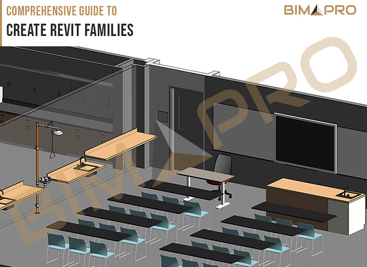
A Comprehensive Guide to Revit Family Creation is the perfect go-to for anyone looking to get comfortable with making custom families in Revit. Creating Revit Families is a crucial skill for anyone involved in Building Information Modeling (BIM), as it lays the foundation for accurate and efficient project workflows. At its core, a Revit Family is more than just a visual representation of an object—it’s a data-rich element designed to be adaptable and reusable across projects. Whether it’s a door, window, furniture piece, or custom element, each family is crafted using a combination of geometry, parameters, and embedded information to meet specific design needs. By mastering Revit Family creation services, designers can enhance project consistency, streamline collaboration, and unlock new levels of design precision. For those looking to maximize efficiency, outsourcing family creation to experts ensures access to high-quality, standardized components while saving time and costs.
Revit Families are an integral part of Autodesk Revit, a software used for BIM modeling services. To understand Revit Families, imagine them as digital representations of real-world building components—like windows, doors, furniture, beams, or even plumbing fixtures. They are essentially templates for creating BIM objects that will appear in a Revit model. These objects are not just shapes; they contain crucial data about the objects they represent, such as dimensions, materials, and functional properties, making them a key component in creating an accurate and detailed digital model of a building.
Each Revit Family consists of various “types,” which are different variations of the same basic object. For example, a “window family” might include types for a 3-foot by 5-foot window, a 4-foot by 6-foot window, and so on. These types allow designers to create multiple variations of the same object without needing to start from scratch each time. This level of customization ensures that the model is tailored to the specific design needs of a project.
There are three main types of Revit Families: System Families, Loadable Families, and In-Place Families. Each serves a different purpose within the Revit environment.
1. System Families
These families are predefined within the Revit software and cannot be created or modified in the same way as other families. System Families include basic architectural, structural, and MEP elements like: Walls, Floors, Roofs, Ceilings, Columns, Foundation elements, etc.
These families are essential building blocks that form the structure of the model. They are typically modified using Revit’s built-in tools (like the Wall tool or Floor tool) but cannot be saved separately or loaded into other projects like Loadable Families.
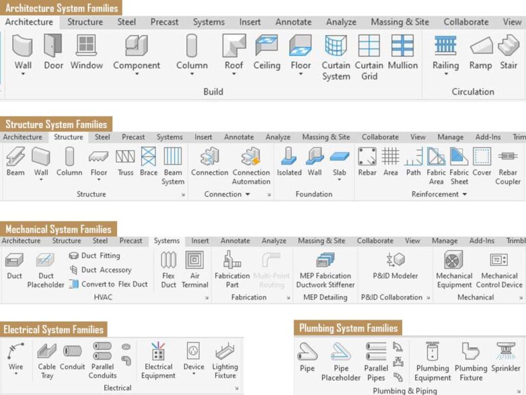
2. Loadable Families
Loadable Families are custom objects that users can create and load into any Revit project. These families are highly versatile and include things like: Doors, Windows, Furniture (chairs, tables), Fixtures (lighting, plumbing), Equipment (HVAC units, appliances).
The beauty of Loadable Families is their reusability—once created, you can save them in a library and use them across multiple projects, ensuring consistency and reducing repetitive work. These families are created from scratch or by modifying existing templates.

3. In-Place Families
In-Place Families are unique to a specific project. These are created when you need a custom element that doesn’t fit into the typical category of a Loadable Family. They are designed directly within the project and cannot be reused across other projects unless they are manually recreated. These families are often used for highly specialized, one-off components, like: Custom sculptures, Special structural elements, Complex and unique building features.
In-Place Families are flexible and can be modified directly within the project, but their lack of reusability makes them less efficient for large-scale BIM operations.
The LOD directly affects the creation of Revit families, as it determines the amount of detail a family should contain and how it will be used in the broader BIM model. Here’s a breakdown of how LOD influences family creation in Revit:
1. LOD 100: Basic Conceptual Families
At LOD 100, Revit families are created for the purpose of demonstrating the concept or massing of the design. The family models in this stage have minimal geometry and are typically represented as simple placeholders or volumes. The primary goal is to provide an overview of the building’s form and function rather than precise specifications.
2. LOD 200: Generic Geometry and Systems Families
At LOD 200, families start to take on more geometric detail. Revit families at this level contain approximate dimensions and may include some additional attributes that help define the size, shape, and location of objects within the model.
3. LOD 300: Detailed and Accurate Families
LOD 300 is where Revit families become fully detailed with accurate geometry and embedded data. Families at this level are typically used for coordination and design development. At this stage, the Revit families contain more complex geometry, material specifications, and dimensions that align closely with the design intent.
.")
4. LOD 400: Fabrication-Ready Families
When a Revit family reaches LOD 400, it is fully detailed and ready for fabrication. These families contain all the necessary information for actual construction, including accurate geometry, material specifications, and installation details. This is the most detailed level before the final as-built model.
5. LOD 500: As-Built Families
LOD 500 represents the final, as-built condition of the project. The Revit families at this level are used to document the final construction details after the building has been completed. They reflect the actual materials, dimensions, and components used in the building, and serve as a record for maintenance and operations.
Read more in detail about BIM LOD (Level of Development) – LOD100 | 200 | 300 | 350 | 400 | 500
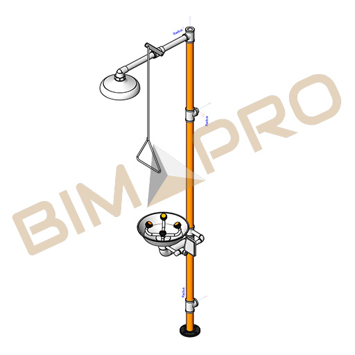
Revit Families are not just visual representations of objects—they contain embedded data that defines their properties, behavior, and relationships with other elements in the model. There is a stramline process to create Revit family. First, you create the geometry, which defines the shape and size of the object in 2D and 3D space. This could be a simple shape, like a rectangular door, or a more complex shape, like a custom light fixture. Once the geometry is defined, you assign parameters to control the object’s behavior. Parameters are like instructions that define how the object should respond to changes. For instance, a door might have parameters to control its width, height, material, or swing direction. These parameters make the family flexible and adaptable to changes in the design.

The next step is adding data to the family. This is where the real power of BIM comes in. Revit Families are not just graphical elements—they are full of embedded information. For example, a piece of furniture might have data about its weight, material, manufacturer, and cost. This data can be used for scheduling, cost estimation, and energy analysis, among other things. It ensures that the entire project is well-coordinated, with accurate data flowing seamlessly between design, construction, and operations.
1.Geometry
Geometry refers to the 3D shape of the family. This is the visual part of the family that you can see in the model. For example, the geometry of a door family includes the door’s width, height, and shape. Geometry can be simple (like a rectangular window) or complex (like a custom lighting fixture). The geometry is typically created in Revit’s Family Editor, where you can design the object’s 2D and 3D forms.
2. Parameters
Parameters are the key to Revit’s parametric design, which allows families to adapt based on user input. These are the dimensions or properties that define how an object behaves and responds to changes in the model. For example:
By using these parameters, families become dynamic. When you change one parameter (like the width of a door), all related aspects of the family (such as its size or material) automatically adjust according to the rules defined in the family.
3. Data (Embedded Information)
Revit Families are rich in data. Along with the geometry, families contain detailed information that is crucial for project coordination. This might include:
This data allows teams to work more efficiently, as it automatically populates schedules, helps in procurement, and ensures that the model contains all necessary details for construction.
Explore Project: Revit Family Creation Services for Building Product Manufactures
Creating a Revit Family requires knowledge of parametric design and understanding how to structure the family’s geometry, behavior, and data. Parametric design refers to using parameters to control an object’s size, shape, and relationships with other objects. For instance, you might create a table family with parameters for height, width, and leg style, so that if the table’s size changes, the design and proportions automatically adjust.
Once a Revit Family is created, it can be saved in a library for reuse across different projects. This ensures consistency, improves efficiency, and reduces errors in future projects. For example, once you’ve created a custom door family, you can reuse it in multiple building designs, adjusting the sizes or materials as needed, but maintaining the same basic design.
Creating Revit Families is a detailed process that involves several stages. Here’s an overview of how you can create a basic Revit Family:
1. Open the Family Editor
The Family Editor is the environment in Revit where you create and modify families. You can access it by creating a new family file. From there, you can start building your family by defining its geometry and parameters.
2. Create Geometry
Start by creating the 2D and 3D shapes that define your family. This can be done using Revit’s drawing tools like lines, arcs, and extrusion commands. For instance, if you’re creating a door family, you’d start by drawing the door panel’s 2D shape and then extrude it into 3D.
3. Assign Parameters
Next, define the parameters that control your family. This includes setting dimensional parameters (e.g., width, height), material parameters (e.g., wood, glass), and any other properties that will make your family flexible.
4. Add Data
If necessary, you can also embed data into the family, such as manufacturer info, cost, and energy performance. This data is important for project coordination and analysis.
5. Load into Project
Once your family is created, you can save it to a library for reuse. You can then load it into any Revit project. When you place the family into the project, you can adjust the instance or type parameters to customize it for your specific needs.

One of the biggest benefits of Revit Families is how they support collaboration in a BIM environment. Since Revit is a multi-disciplinary tool, all team members—from architects to structural engineers to MEP specialists—can work with the same families, ensuring that the design is consistent across all disciplines. This reduces errors and miscommunications and helps with coordination, as any changes made to a family (such as changing the material or dimensions of a door) will automatically update in the entire model.
Using Revit Families offers several benefits within the BIM workflow:
1. Consistency: Families ensure that all components in the model are uniform, reducing errors and discrepancies.
2. Efficiency: Once created, families can be reused across multiple projects, saving time and effort.
3. Data Integration: Families contain embedded data that can be used for scheduling, analysis, and cost estimation, making the BIM model a comprehensive source of information.
4. Collaboration: Since families are standardized, all team members—whether architects, engineers, or contractors—can work with the same components, ensuring better coordination and fewer misunderstandings.
For firms without dedicated BIM teams, outsourcing is a cost-effective solution. BIM Services provider can create high-quality, standardized families that align with your needs, freeing up your team to focus on core design activities. Outsourcing also ensures access to experts who stay updated on the latest trends and standards. Outsourcing BIM content creation Services can be a strategic decision that offers numerous benefits for companies. Here’s how it can save both time and costs:
Outsourcing allows you to tap into a pool of experts who specialize in BIM content creation. They are proficient in creating high-quality models, families, and components according to industry standards. This eliminates the need for training internal staff or hiring specialized talent, saving both time and money.
Outsourcing partners often have dedicated teams working on your projects, leading to faster delivery times. Since they focus on content creation, they can handle large volumes of work simultaneously, ensuring quicker project completion and reducing delays on your end.
Outsourcing enables companies to avoid the overhead costs associated with hiring full-time employees, such as salaries, benefits, and training. Instead, you pay for the work done, typically on a contract or per-project basis, which can be more cost-effective than maintaining a large internal team.
As project demands fluctuate, outsourcing provides the flexibility to scale your BIM content creation team up or down without the need for long-term commitments. Whether you need additional help for a short-term project or ongoing support, outsourcing provides the ability to adjust quickly.
Outsourcing to professionals who are experienced with BIM standards reduces the chances of errors in content creation. These experts understand the intricacies of proper modeling, data management, and file formatting, resulting in fewer revisions and rework.
By outsourcing repetitive or specialized tasks like BIM content creation, your internal team can focus on higher-value activities, such as project management, design, and strategic planning. This improves overall productivity and optimizes resource allocation.
Outsourcing firms often have access to the latest BIM software and technologies, which may be costly for smaller companies to maintain internally. This means you get access to cutting-edge tools without having to invest in new software or infrastructure.
Reputable outsourcing partners implement strict quality control processes, ensuring that the BIM content created meets your standards consistently. They follow best practices and adhere to industry regulations, which can improve the overall quality of the content and reduce the need for revisions.
For beginners, learning how to create Revit Families can be challenging but is an essential skill to master in BIM. Once you get the hang of it, it opens up many possibilities for creating customized, reusable, and highly detailed BIM content. It also ensures that the model is both accurate and efficient, providing valuable data for everything from construction to facilities management. As you progress, you’ll be able to create more advanced families, optimize your designs, and streamline your workflow, ultimately contributing to better project outcomes and faster delivery times.
Understanding and mastering Revit Families is crucial for anyone working in BIM. Families are not just graphical elements; they are rich with data and designed to be flexible, dynamic, and reusable. By learning how to create, modify, and utilize Revit Families effectively, you’ll be able to create detailed, accurate models that enhance design, construction, and collaboration, ultimately leading to better project outcomes. Whether you’re an architect, engineer, or contractor, mastering Revit Families will elevate your ability to work efficiently in a BIM environment.
Looking for expericenced Revit Family Creation Services Provider? Contact Us

BIMPRO, LLC, a BIM services provider in Texas, was tasked with delivering comprehensive BIM modeling services for a prominent 5-story Hotel construction project in the Florida state. The project aimed to create a modern and efficient Hotel facility, adhering to the highest standards of quality and sustainability. We played a crucial role in facilitating efficient design, collaboration, and coordination through the implementation of BIM technology at various stages of the project.


BIMPRO, LLC provided a comprehensive range of architectural BIM services throughout the project’s design phases, primarily utilizing AutoCAD and Revit for modeling and documentation.
A well-defined BIM execution plan was established and followed throughout the project. This plan outlined the following key aspects:
The well-executed BIM plan and the use of AutoCAD and Revit significantly contributed to the efficient delivery of the project, meeting deadlines and budgets.
In short, BIMPRO played a pivotal role in the success of our educational project. We couldn’t have asked for a more professional, knowledgeable, and dedicated team to bring our vision to life. We highly recommend their services to anyone in need of top-notch BIM expertise.
– Architect Principal

The architecture, engineering, and construction (AEC) industry has seen rapid advancements in technology, especially with the adoption of Building Information Modeling (BIM). As these industries evolve, the tools we use for project management and collaboration must adapt. In a groundbreaking development, Newforma recently acquired BIM Track, merging the strengths of both platforms into Newforma Konekt. This unified tool is transforming how project teams manage information, resolve issues, and improve efficiency in BIM workflows.
In this blog, we’ll explore the evolution of Newforma Konekt, its role in modern BIM workflows, and how its integration with BIM Track enhances collaboration, issue management, and project success.

The Power of Issue Management in BIM!! BIM Track is a cloud-based issue tracking and collaboration platform tailored for the architecture, engineering, and construction (AEC) industry to improve communication and coordination in Building Information Modeling (BIM) workflows. Designed to integrate seamlessly with popular design and construction software like Revit, Navisworks, AutoCAD, and Tekla, BIM Track enables teams to identify, manage, and resolve issues efficiently throughout the project lifecycle.
The platform acts as a centralized hub where stakeholders can log, track, and prioritize issues, ensuring that every team member has access to up-to-date information, regardless of their location. With its robust reporting and analytics features, BIM Track offers insights into project performance, helping teams identify bottlenecks and streamline workflows. It also facilitates accountability by assigning issues to specific team members and tracking their resolution progress.
BIM Track supports open standards like BCF (BIM Collaboration Format), making it compatible with a wide range of software tools and fostering interoperability across disciplines. By enhancing transparency, reducing rework, and improving communication, BIM Track contributes to delivering projects on time and within budget.
In May 2023, Newforma, a leader in project information management (PIM) solutions for the architecture, engineering, and construction (AEC) industry, acquired BIM Track, a prominent cloud-based collaboration platform specializing in issue tracking and BIM coordination. This acquisition represents a strategic move by Newforma to enhance its offerings in project and team collaboration by integrating BIM Track’s advanced issue management and communication capabilities into its platform.
By combining Newforma’s robust project data organization tools with BIM Track’s powerful issue tracking and real-time collaboration features, the merger aims to streamline workflows across the AEC industry. The integration strengthens the ability to manage and resolve design and construction issues while promoting interoperability across multiple software environments through open standards like BCF (BIM Collaboration Format).
This unified platform ensures improved coordination, transparency, and accountability, enabling teams to work more efficiently and deliver higher-quality outcomes. For BIM Track, joining Newforma expands its reach and reinforces its commitment to fostering cross-disciplinary collaboration, solidifying its role as a key player in advancing BIM workflows
The AEC industry relies on seamless communication and collaboration among stakeholders. By acquiring BIM Track, Newforma enhances its ability to facilitate real-time issue management and discussion, bridging the gap between design, construction, and operation teams.
BIM Track’s robust integrations with tools like Autodesk Revit, Navisworks, and Tekla Structures make it a natural fit for Newforma’s portfolio. The acquisition ensures that project data, issues, and documentation are seamlessly linked across platforms.
With BIM Track’s established presence in the BIM community, Newforma extends its market influence and strengthens its reputation as a leader in AEC project management.
Revolutionizing Project Management in BIM!! Newforma Konekt, the result of Newforma’s acquisition of BIM Track, is a cloud-based collaboration platform designed to streamline communication, document management, and issue resolution for the AEC industry. It connects all project stakeholders—architects, engineers, contractors, and owners—into a centralized environment, ensuring smoother workflows and greater accountability.
Newforma Konekt is built specifically for BIM workflows and it integrates seamlessly with leading BIM tools such as Autodesk Revit and Navisworks, making it an essential tool for any modern construction project.
Newforma Konekt addresses the growing need for effective communication and issue management within BIM projects. It is particularly useful in large-scale, complex construction projects where coordination between multiple teams and disciplines is critical. Here’s how Newforma Konekt fits into the BIM workflow:
1. Centralized Communication
Those days of fragmented emails and lost messages are gone. Newforma Konekt centralizes all project communication in one platform. This enhances transparency, reduces confusion, and ensures everyone is on the same page.
2. Real-Time Issue Tracking and Management
One of the standout features of Newforma Konekt is its issue tracking system. Project teams can track and manage issues in real time, linking them directly to specific elements in the BIM model. This ensures that problems are addressed promptly, minimizing delays and rework.
3. Improved Accountability
Clear documentation of roles and responsibilities within Newforma Konekt helps teams avoid miscommunication. With accountability built into the system, tasks are assigned efficiently, and deadlines are met more reliably.
4. Seamless Integration with BIM Tools
Newforma Konekt integrates effortlessly with popular BIM software like Autodesk Revit and Navisworks, allowing for a smooth data exchange between platforms. This integration ensures that issues, project data, and documents are all connected, reducing the potential for errors or misalignment.
By leveraging Newforma Konekt, BIM service providers can enhance their project delivery capabilities, reduce errors, and improve efficiency. This makes it a valuable tool for companies like BIMPRO LLC, aiming to offer top-tier BIM modeling services.

Image Source: https://konekt.help.newforma.com/
The combination of Newforma’s project management expertise and BIM Track’s issue management capabilities creates a tool that addresses key pain points in AEC project workflows. Let’s explore some of the features that make Newforma Konekt invaluable:
1. Issue Management
Issues can be tracked directly within the BIM environment, tied to specific elements in the model. This ensures that issues are clearly identified and resolved quickly, preventing them from snowballing into bigger problems later in the project.
2. Enhanced Collaboration
By providing a shared platform for all stakeholders, Newforma Konekt minimizes communication silos. Teams can easily collaborate in real time, reviewing the same data and providing input across different disciplines, whether they’re in the field or working remotely.
3. Document Control
Newforma Konekt serves as a central repository for all project files. From plans to reports, team members can access the most up-to-date documents at any time, reducing the risk of working from outdated versions.
Step 1: Install and Configure the Platform
Start by setting up your Newforma Konekt account and configuring it according to your project needs. Ensure it is integrated with your primary BIM tools like Revit or Navisworks for seamless data exchange.
Step 2: Train Your Team
Conduct training sessions for all stakeholders to familiarize them with Newforma Konekt’s features, including issue tracking, document sharing, and communication tools.
Step 3: Define Roles and Permissions
Assign roles and permissions within the platform to ensure accountability. This prevents unauthorized changes and streamlines workflows.
Step 4: Link Issues to BIM Models
Leverage the integration to link issues directly to model elements. This feature ensures that all issues are contextualized, making them easier to address.
Step 5: Monitor and Optimize
Regularly review the platform’s performance and collect feedback from users. Use insights to optimize workflows and ensure maximum efficiency.

Newforma Konekt is more than just a project management tool—it’s a game-changer for the AEC industry. Its integration with BIM ensures that teams can collaborate efficiently, resolve issues faster, and deliver higher-quality projects.
For AEC professionals looking to stay competitive in an evolving industry, adopting tools like Newforma Konekt is no longer optional—it’s essential. By streamlining workflows and fostering collaboration, it paves the way for a future where construction projects are not only completed on time but exceed expectations.
Reach out to BIMPRO LLC for BIM services at info@bimprous.com or +1 (346) 508-6588!


BIMPRO has provided MEP clash coordination services for a high-rise apartment project in Houston, Texas. We produced a precise, detailed, and coordinated BIM model for architectural and MEP disciplines from the earlier phase of design (schematic design and design development) to the construction documents set.
Services Provided: Architectural BIM Services, MEP BIM Services, Clash Detection Services, BIM Coordination Meetings
Building Type: Residential
Project Location: Houston, TX
Area: Approx. 230,000 sq. ft.
Software: Revit, AutoCAD, Navisworks
1,000+
Successful Projects
5+
Years of Experience
10+
Sectors Served
Project Description:
This project is a 17-story high-rise apartment building located in the Houston, Texas. The BIM requirements included developing precise Revit models for both the Architectural and MEP components based on input from the architects and MEP designers. The client expected weekly clash analyses and clash reports generated in Navisworks to support BIM coordination meetings. BIMPRO provided rapid and high-quality responses to all client requests, ensuring adherence to the project schedule and maintaining model accuracy with minimal clashes.
Despite tight deadlines, daily communication and quick responses to any design changes or markups allowed us to produce an exceptionally accurate model. BIMPRO identified and resolved thousands of clashes, resulting in minimal RFIs and change orders. Our expertise in modeling accuracy and efficient clash detection and resolution helped the client save considerable time and costs.

When you’re managing a BIM project, the software tools you choose can make a world of difference. Navisworks and Revizto are two major players in this space, each with its own strengths and weaknesses. Whether you’re focused on detailed clash detection or ensuring your team is always on the same page, understanding what each tool offers is key to making the right choice. Let’s dive into a detailed comparison of Navisworks and Revizto to help you decide which one suits your project needs.
When you’re managing a BIM project, the software tools you choose can make a world of difference. Navisworks and Revizto are two major players in this space, each with its own strengths and weaknesses. Whether you’re focused on detailed clash detection or ensuring your team is always on the same page, understanding what each tool offers is key to making the right choice. Let’s dive into a detailed comparison of Navisworks and Revizto to help you decide which one suits your project needs.
While Navisworks is all about detailed technical analysis, Revizto is designed to make collaboration effortless. It’s a tool that prioritizes keeping your team connected and ensuring everyone has access to the latest project information—regardless of their technical background.
Both Navisworks and Revizto bring unique strengths to BIM coordination and clash detection. Navisworks is your go-to for detailed, in-depth analysis, making it indispensable for projects where technical accuracy is paramount. Contact BIMPRO LLC for clash detection Services. Revizto, on the other hand, is all about making collaboration seamless and ensuring that every team member, regardless of their technical expertise, can contribute effectively.
By carefully considering your project’s needs and the strengths of each tool, you can make an informed decision that enhances your BIM workflow, minimizes risk, and ensures successful project delivery.
Looking for expert BIM Modeling Services, reach out to BIMPRO LLC.


We have provided Scan to BIM services for a warehouse project located in Jacksonville, Florida. We have converted point cloud file into BIM model and have modeled LOD 300 detailing for mechanical, electrical, plumbing and fire protection disciplines. Our model depicted accurate as-build modeling as per point cloud captures and site verified dimensions.
Services Provided: Scan to BIM Conversion, MEP Modeling
Building Type: Warehouse
Project Location: Jacksonville, Florida
Area: Approx. 11,400 sq. ft.
Software: Revit